Connection Diagram
2-3
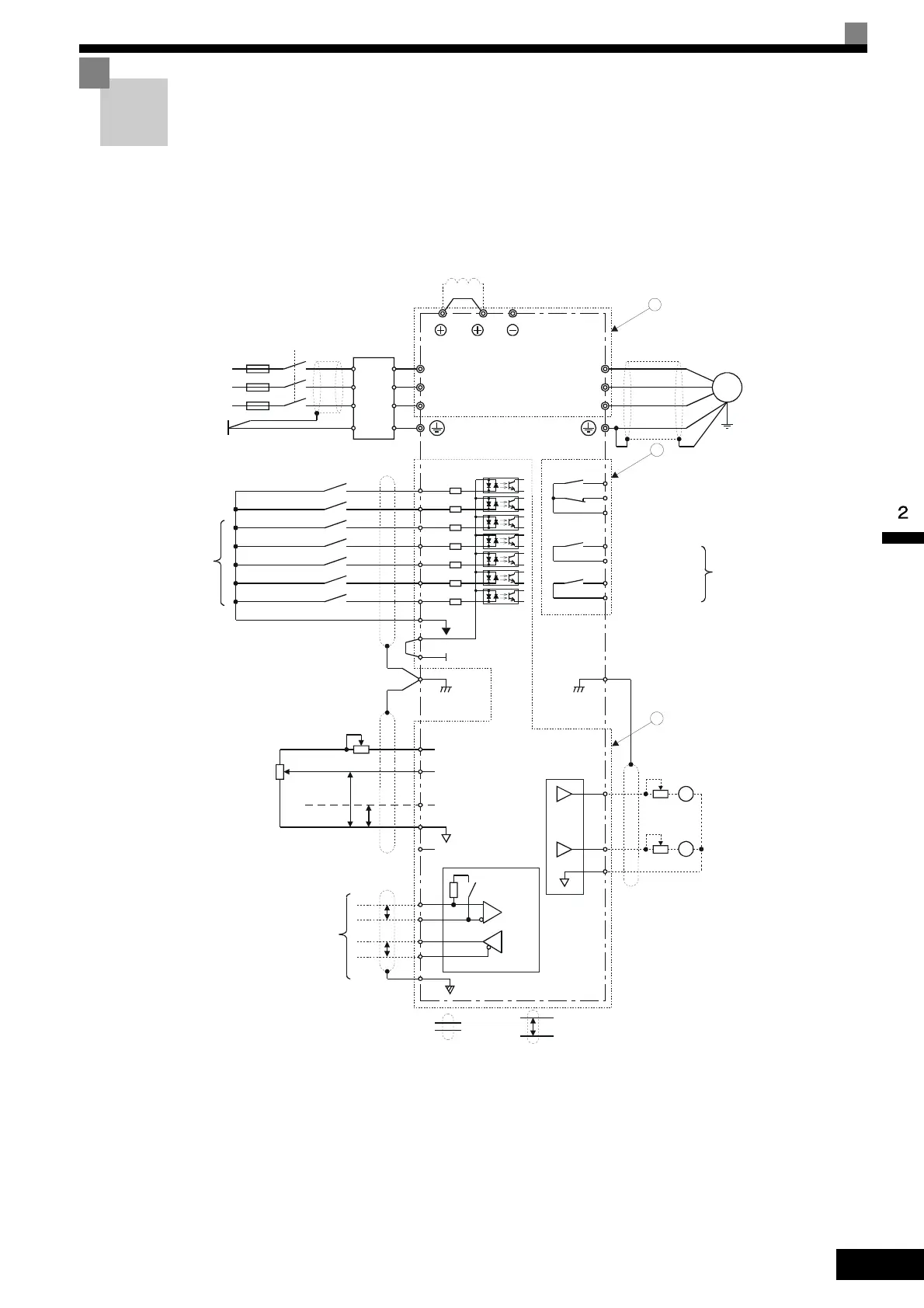
Connection Diagram
The connection diagram of the Inverter is shown in Fig 2.2.
When using the Digital Operator, the motor can be operated by wiring only the main circuits.
Fig 2.2 Connection Diagram (Model CIMR-E7C47P5 Shown Above)
M2
M1
Contact output 1
[Default: During run]
M4
M3
Contact output 2
[Default: Zero speed]
MC
MB
Fault contact output
250 VAC, 1A max.
30 VDC, 1A max.
MA
Multi-function digital
output
250 VAC, 1A max.
30 VDC, 1A max.
Line
Filter
L1
L2
L3
PE
IM
3-phase power supply
380 to 480 V
50/60 Hz
Varispeed E7
CIMR-
E7C47P5
Forward Run/Stop S1
R/L1
S/L2
T/L3
U/T1
V/T2
W/T3
Reverse Run/Stop S2
S3External fault
S4
Fault reset
S5
Multi-step speed setting 1
S6
S7
SN
Multi-step speed setting 2
Jog frequency selection
Fuse
SC
SP
24V
Multi-function
digital inputs
[Factory settings]
+V
C
2
Multi-function analog Input 1:
[Default: Frequency Bias
4 to 20mA (250 )]
Ω
Analog Input 1: Master
frequency reference
0 to 10V (20k )
Ω
A1
0V
Analog input power supply
+15V, 20mA
E(G)
Shield
terminal
PP
4 to 20mA
0 to 10V
2k
Ω
Adjustment
3
2k
Ω
E(G)
FM
+
-
M
+
-
C
M
FM
djustment,
20 k
Ω
djustment,
20 k
Ω
Multi-function analog output 1
(0 to 10V, 2mA)
[Default: Output frequency, 0 to 10 V]
Multi-function analog output 2
(0 to +10V, 2mA)
[Default: Output current, 0 to 10 V]
Shield
terminal
R+
R-
S+
S-
IG
Terminating
resistance
DC reactor to improve input
power factor (optional)
Short-circuit bar
1 2
UX
Shielded wires P
Twisted-pair
shielded wires
MEMOBUS
communication
RS-485/422
P
P
2
1
Main
contactor
Motor
-V
Analog input power supply
-15V, 20mA
1
2
3
Artisan Technology Group - Quality Instrumentation ... Guaranteed | (888) 88-SOURCE | www.artisantg.com
 Loading...