Individual Functions
6-95
Setting the V/f Pattern
Using the E1- constants the Inverter input voltage and the V/f pattern can be set as needed. It is not rec-
ommended to change the settings when the motor is used in open loop vector control mode.
Related Constants
* 1. These are values for a 200 V Class Inverter. Values for a 400 V Class Inverter are double.
* 2. The contents of constants E1-11 and E1-12 are ignored when set to 0.00.
Setting Inverter Input Voltage
Set the Inverter input voltage correctly in E1-01 so that it matches the power supply voltage. This set value
will be the reference value for the protection functions and similar functions (overvoltage level, stall level).
Setting V/f Pattern
The V/f pattern can be selected using constant E1-03. There are two methods of setting the V/f pattern: Select
one of the 14 preset pattern types (set value: 0 to E), or set a user-defined V/f pattern (set value: F).
The factory setting for E1-03 is F.
To select one of the existing patterns, refer to the following table.
Con-
stant
Number
Name Description
Setting
Range
Factory
Setting
Change
during
Opera-
tion
Access
Level
E1-01 Input voltage setting
Sets the Inverter input voltage. This setting is used as a ref-
erence value for protection functions.
155 to
255
*1
200 V
*1
No Q
E1-03 V/f pattern selection
0 to D: Select from the 14 preset V/f patterns.
F: Custom user-set patterns (Applicable for setting of
E1-04 to E1-10.)
0 to F F No Q
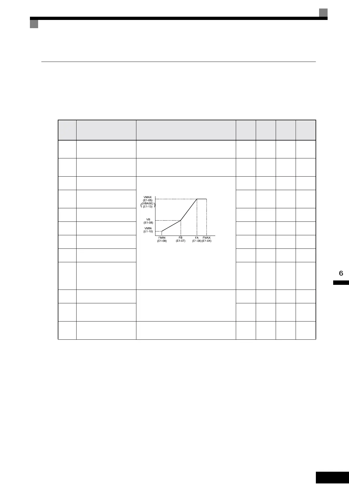
E1-04 Max. output frequency (FMAX)
To set V/f characteristics in a straight line, set the same
values for E1-07 and E1-09. In this case, the setting for
E1-08 will be disregarded.
Always ensure that the four frequencies are set in the fol-
lowing manner:
E1-04 (FMAX) ≥ E1-06 (FA)
>E1-07 (FB) ≥ E1-09 (FMIN)
40.0 to
200.0
50.0 Hz No Q
E1-05 Max. voltage (VMAX)
0.0 to
255.0
*1
200.0 V
*1
No Q
E1-06 Base frequency (FA)
0.0 to
200.0
50.0 Hz No Q
E1-07 Mid. output frequency (FB)
0.0 to
200.0
2.5 Hz No A
E1-08
Mid. output frequency voltage
(VB)
155 to
255*1
15.0 V
*1
No A
E1-09 Min. output frequency (FMIN)
0.0 to
200.0
1.2 Hz No Q
E1-10
Min. output frequency voltage
(VMIN)
0.0 to
255.0
*1
9.0 V
*1
No A
E1-11 Mid. output frequency 2
Set only to fine-adjust V/f for the output range. Normally,
this setting is not required.
0.0 to
200.0
0.0 Hz
*2
No A
E1-12 Mid. output frequency voltage 2
0.0 to
255.0
*1
0.0 V No A
E1-13 Base voltage (VBASE) Sets the output vltage at the base frequency (E1-06)
0.0 to
255.0
*1
0.0 V No A
Output voltage (V)
Frequency (Hz)
Artisan Technology Group - Quality Instrumentation ... Guaranteed | (888) 88-SOURCE | www.artisantg.com
 Loading...