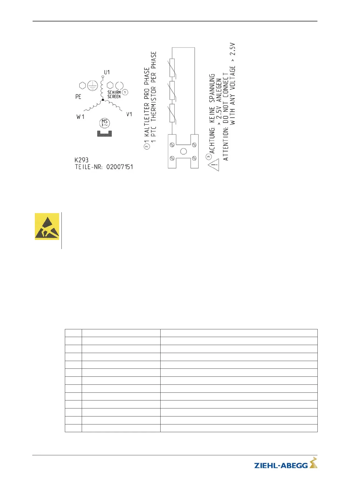
5.3.7 Connection diagram
1Screen
2 1 PTC thermistor per phase
3 Attention: Do not apply any voltage > 2.5 V!
5.4 Absolute encoder
Caution!
Never touch the connection contacts on the position absolute encoder or on the cable! The electronics can be
destroyed by static electricity.
You must discharge your own body before touching. This can be done, for example, by touching a conductive,
earthed object (e.g. bare metal switch cabinet parts) immediately before.
Operation of the elevator machine without an absolute encoder is not permissible.
Note:
Removal of the absolute value encoder is only possible from the rear. Due to the extremely low failure
rate of the absolute value encoder, this does not represent a problem.
5.4.1 Cable length
•
Cable length maximum 25 m
•
Shielded twisted pair cable
5.4.2 Contact assignment
SV120 circular connector to absolute value encoder ECN1313 (ZIEHL-ABEGG SE Standard)
Pin
Signal Designation
A DATA Data line for communication with the absolute encoder
B DATA / Data line inverse
C 5 V Sensor Up Sensor cable for encoder voltage (5 V positive)
D 5 V Up Controlled +5 V voltage supply (positive)
E 0 V Un Ground voltage supply absolute encoder (negative)
F B+ (sine) Analog track B (sine)
G CLOCK / Clock signal invers
H CLOCK Clock signal for serial transfer
J 0 V Sensor Un Sensor cable for encoder voltage (negative)
K A+ (cosine) Analog track A (cosine)
L A- (cosine inverse) Analog track A invers (cosine invers)
M B- inverse (sine inverse) Analog track B invers (sine invers)
Translation of the original operating instructions
ZAtop – model series SM210.60B/SM210.70B Electrical installation
$7%$B*% ,QGH[ Part.-No. 01013389-GB (EU-BD 1014)
17/88
 Loading...