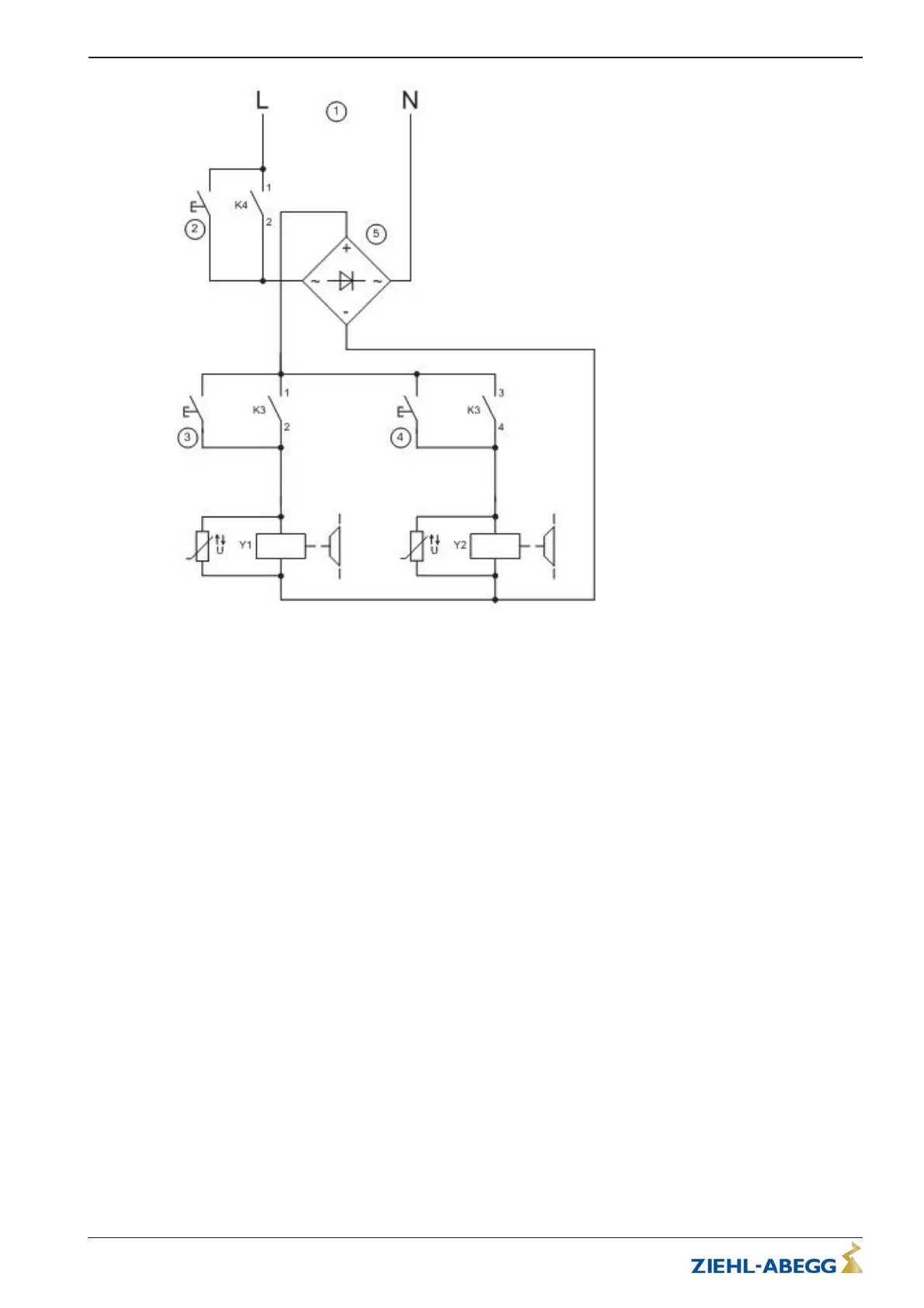
Simplified diagram for brake control
1 Voltage supply
2 Button two circuit test
3 / 4 “Open brake” button
5Rectifier or fast-acting rectifier
K3 Brake contactor, activated by safety circuit
K4 Brake contactor, activated by control or frequency inverter
5.5.5 Connection
•
The terminal box for the brake may be removed from the elevator machine and mounted on site for
a better attainability.
•
The brake is only allowed to be supplied with power when fastened to the motor and after having
connected
the protective conductor of the motor at the control and the motor side.
•
The brakes have to be protected against over voltage from switching by varistors. The brakes are
supplied with varistors ex factory.
Translation of the original operating instructions
ZAtop – model series SM210.60B/SM210.70B Electrical installation
$7%$B*% ,QGH[ Part.-No. 01013389-GB (EU-BD 1014)
19/88
 Loading...