5.4.3 Offset
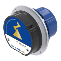
Unless otherwise agreed, the absolute value encoder offset is set to 0. This is achieved by
connecting DC voltage with U to + and V and W to -.
The absolute value encoder may not be mechanically detached to ensure that the factory settings
are not lost. If the absolute value encoder has been detached, a new absolute value encoder
calibration must be performed with the frequency inverter. For details of the procedure, refer to the
frequency inverter operating instructions.
5.5 Brake
Brake type RTW 1000
•
Also refer to the operating instructions for the brake.
5.5.1 Application
•
The brakes are intended for static applications as holding brakes. Dynamic braking must be
restricted to emergency and inspection braking. No wear occurs on a holding brake. This means
that the brake is maintenance free, and only the air gap has to be checked as described in the
“Maintenance and repair - Inspection intervals - Checking the air gap” chapter.
5.5.2 Mechanical releasing
Mechanical release of the brakes is possible.
A brake with a mechanical hand release system is available optionally. The hand release system
cannot be fitted later. The complete brake must be replaced to retrofit the hand release system.
The brake circuits can be opened separately with mechanical hand release.
5.5.3 Release monitoring
•
The brake release monitoring serves as monitoring for redundancy and the operation status of the
br
akes.
•
Release monitoring for the brakes is carried out by a microswitch or inductive proximity switch. For
technical data, see chapter "Appendix - Technical data - Microswitch or inductive proximity switch".
5.5.4 Control
5.5.4.1 Contactorless - ZAsbc4
Electronic and noise-free activation of the brake.
The brake operating mode is set on site.
For information on installation and commissioning, refer to the ZAsbc4 operating instructions.
5.5.4.2 Electromechanical contactors
Different rectifiers need to be used depending on the brake operating mode:
•
Brake without overexcitement (operating voltage 207 VDC: Bridge rectifier
To reduce noises during brake disconnect the brakes should be switched to the alternating current
side (K4), while normal operation. The brakes are switched-off slower and thus quieter through the
rectifier.
To ensure instantaneous brake engagement in emergencies, during inspection runs and return
runs,a second contactor (K3), which disconnects the brake on the direct current side, is used. This
contactor is to be switched depending on the safety circuit.
Translation of the original operating instructions
ZAtop – model series SM210.60B/SM210.70B Electrical installation
$7%$B*% ,QGH[ Part.-No. 01013389-GB (EU-BD 1014)
18/88
 Loading...

