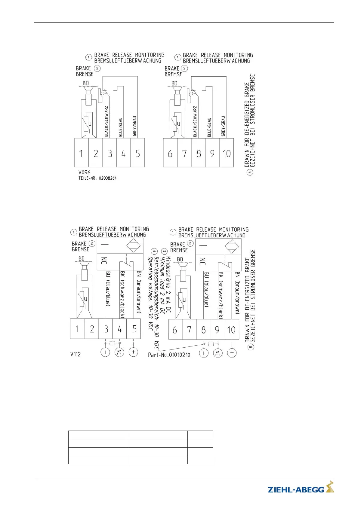
5.5.6 Connection diagram
Brake wiring diagram with micro switch
1 Brake air monitoring
2Brake
3 Shown with currentless brake
Brake wiring diagram with inductive proximity switch
1 Brake air monitoring
2Brake
3 Minimum strength 2 mA DC
4 Operating voltage range 10 - 30 V DC
5 Shown with currentless brake
5.6 Forced cooling
The forced ventilation is optional and can be added afterwards.
5.6.1 Technical data
Voltage 220 - 240 [V]
Frequency 50 / 60 [Hz]
Power 50 / 50 [W]
Current 0.24 / 0.23 [A]
Translation of the original operating instructions
ZAtop – model series SM210.60B/SM210.70B Electrical installation
$7%$B*% ,QGH[ Part.-No. 01013389-GB (EU-BD 1014)
20/88
 Loading...