16. Screw on the fixing plate (6) with both hexagon head screws M8 x 16 - 8.8 (7) using a screw
wr
ench SW 13.
Tightening torque: 23 Nm
17. Bundle the connection cables (5) of the magnet coils and the release monitoring and lead it int
o
t
he terminal box (17).
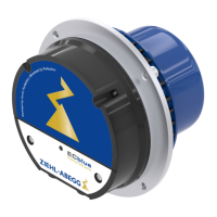
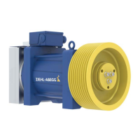
18. Connect the magnet coils, the release monitoring and the varistors (4) according to the wiri
ng
di
agram (18) in the top cover of the connection box (17).
19. Fit strain reliefs (3).
20. Close the terminal box cover (1).
21. Perform brake test (see chapter "Brake operating instructions - brake test" in the appendix).
22. Mount the absolute encoder (see chapter "Replacement of the absolute encoder").
8.3.2.4 Functional test on microswitch/inductive proximity switch for release monitor
After mounting of the brake, a functional test must be performed on the micro switches/inductive
proximity switches (see chapter "Brake operating instructions - release monitor").
If the function is not available, please check the causes that may prevent the actuation of the micro
switches/inductive proximity switches (see chapter "Brake operating instructions - release monitor" in
the appendix). The micro switches/inductive proximity switches will otherwise have to be readjusted
(see the chapter "Assembly and adjustment of release monitor with micro switches or inductive
proximity switches" in the appendix).
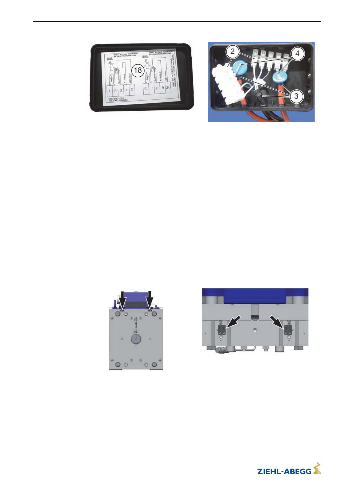
8.3.2.5 Adjustment of the microswitch/inductive proximity switch for release monitor
Adjustment of the microswitches/inductive proximity switches is only necessary if they are not working
correctly.
The microswitches/inductive proximity switches are located on top of the brake (see arrow).
ATTENTION! It must be ensured that the appropriate microswitches/inductive proximity
switches are selected for the magnet to be adjusted.
Adjustment of the release monitor with microswitches/inductive proximity switches, see “Assembly
and adjustment of release monitor with microswitches or inductive proximity switches” chapter in the
appendix.
Translation of the original operating instructions
ZAtop – model series SM210.60B/SM210.70B Service and maintenance
$7%$B*% ,QGH[ Part.-No. 01013389-GB (EU-BD 1014)
37/88
 Loading...