172 ACH580 E-Clipse bypass and packaged drive user manual
Fieldbus adapter
Bypass relay output control
Using the fieldbus for relay output control requires:
• Bypass parameter values set as defined below.
• Fieldbus controller supplied, binary coded, relay command(s) in the appropriate
location. (The location is defined by the Protocol Reference, which is protocol
dependent.)
Note: Relay status feedback occurs without configuration as defined below.
Communication fault
When using fieldbus control, specify the bypass action if communication is lost.
Diagnostics – FBA
Fault Handling
The ACH580 or E-Clipse provides fault information as follows:
• The control panel display shows a fault code and text. See Diagnostics starting on
page 185 for a complete description.
• Parameters 0401 LAST FAULT, 0402 PREVIOUS FAULT1 and 0403 PREVIOUS
FAULT2 store the most recent faults.
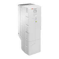
Bypass Parameter Value Description
Protocol
Reference
Modbus TCP
1401 RELAY OUTPUT 1 16
(COMM
CTRL)
Relay Output 1 controlled by fieldbus. 433031 bit 0
1402 RELAY OUTPUT 2 Relay Output 2 controlled by fieldbus.
1403 RELAY OUTPUT 3 Relay Output 3 controlled by fieldbus.
1410 RELAY OUTPUT 4 Relay Output 4 controlled by fieldbus. 433031 bit 3
1411 RELAY OUTPUT 5 Relay Output 5 controlled by fieldbus.
Bypass Parameter Value Protocol Reference
0122 RO 1-3 STATUS Relay 1…3 status. 400278
0123 RO 4-5 STATUS Relay 4…5 status. 400279
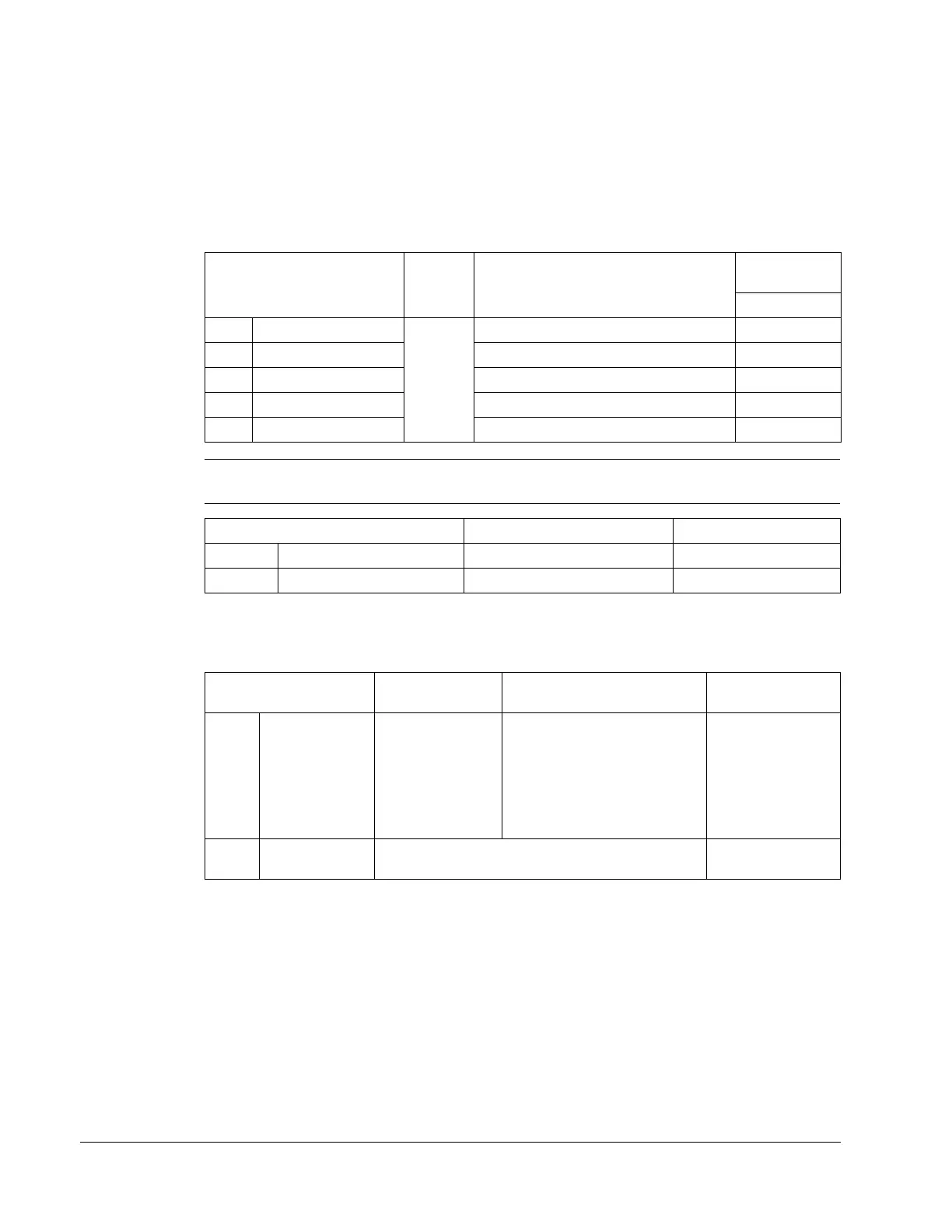
Drive Parameter Value Description
Protocol
Reference
50.02 FBA A COMM
LOSS FUNC
0 = No action
1 = Fault
2 = Last speed
3 = Speed ref safe
4 = Fault always
5 = Warning
Set for appropriate drive/
bypass response. NOTE: If the
system is in bypass mode
when communication is lost,
choices 2 and 3 will cause the
bypass contactor to remain in
its present state.
–
50.03 FBA A COMM
LOSS T OUT
Set time delay before acting on a communication
loss.
–
 Loading...