Defines the delay for the Zero speed delay function. The function is useful in
applications where a smooth and quick restarting is essential. During the
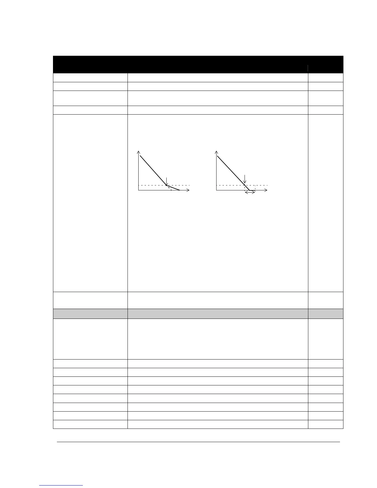
delay the drive knows accurately the rotor position.
No Zero speed delay With Zero speed
d
e
l
ay
Speed Speed
Modulator switched Modulator remains live. Motor
off: Motor coasts to is decelerated to true 0
stop. speed.
Zero speed Zero speed
t
Delay
t
Zero speed delay can be used, for example, with jogging function (parameter
1010 JOGGING SEL).
No Zero speed delay
The drive receives a stop command and decelerates along a ramp. When the
motor actual speed falls below an internal limit (called Zero speed), the
modulator is switched off. The inverter modulation is stopped and the motor
coasts to standstill.
With Zero speed delay
The drive receives a stop command and decelerates along a ramp. When the
actual motor speed falls below an internal limit (called Zero speed), the zero
speed delay function activates. During the delay the functions keeps the
modulator live: The inverter modulates, motor is magnetized and the drive is
ready for a quick restart.
Defines the source from which the drive reads the signal that selects
between two ramp pairs, acceleration/deceleration pair 1 and 2.
Ramp pair 1 is defined by parameters 2202 ACCELER TIME 1, 2003
DECELER TIME 1 and 2204 RAMP SHAPE 1.
Ramp pair 2 is defined by parameters 2205 ACCELER TIME 2, 2206
DECELER TIME 2 and 2207 RAMP SHAPE 1.

 Loading...


