EasyManua.ls Logo

ABB ACS150 series User Manual

ABB ACS150 series
173 pages
To Next Page IconTo Next Page
To Previous Page IconTo Previous Page
Page #167 background imageLoading...
Page #167 background image
164
Appendix: Process PID control
.
PID sleep functionality
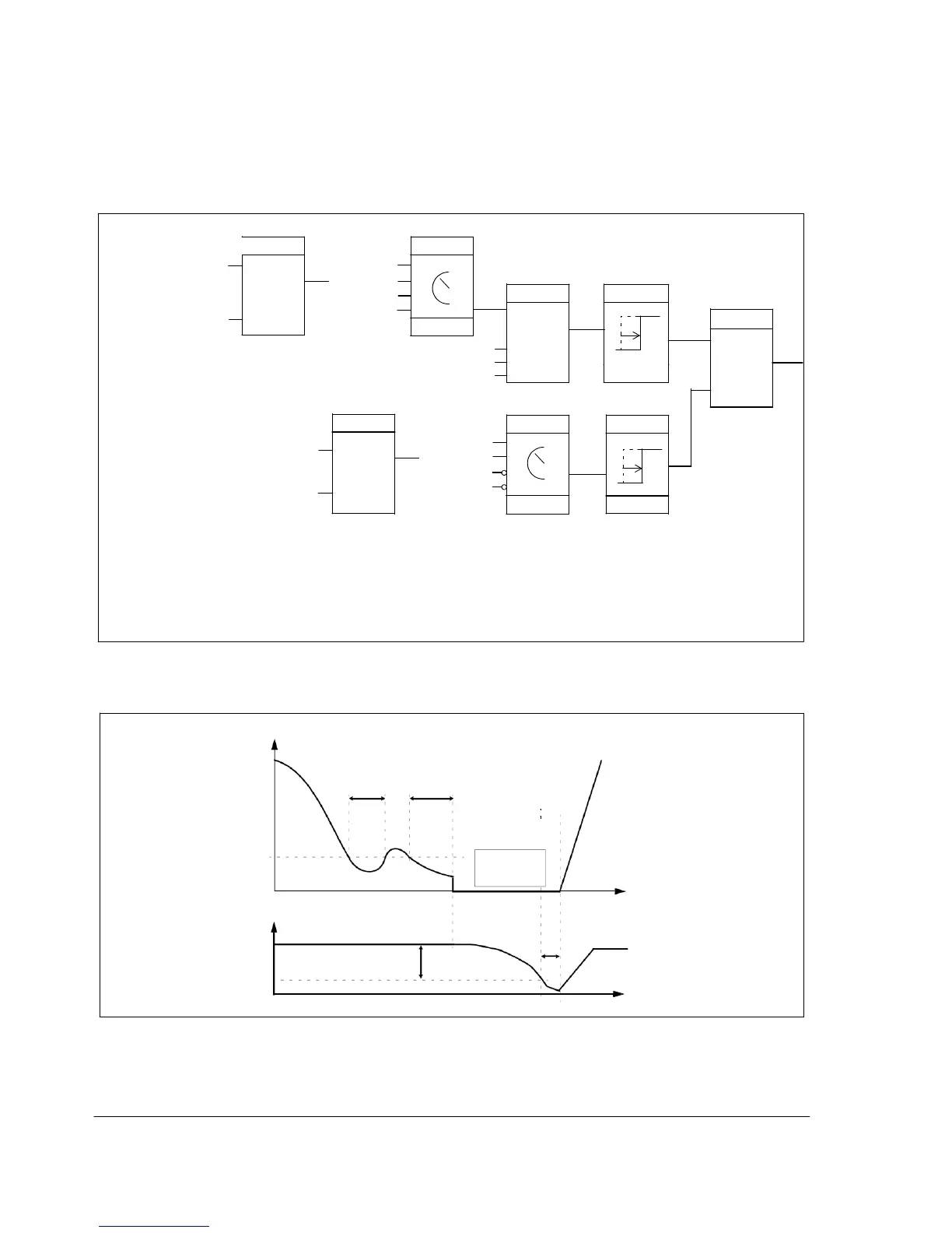
The block diagram below illustrates the sleep function enable/disable logic. The
sleep function can be put into use only when the PID control is active.
output
frequency
Compare
1
NOT SEL
INTERNAL
Select
1<2
DI1
And
.
Delay
4023
2
.
4022
%refActive
&
PIDCtrlActive
modulating
t
4024
Set/Reset
S
S/R
1)
R
0132
Compare
1
1>2
NOT SEL
INTERNAL
D
I
.
1
.
Select
Delay
t
4025
2
.
4022 4026
1) 1 = Activate sleeping
0 = Deactivate sleeping
%refActive: The % reference (EXT REF2) is in use. See parameter 1102 EXT1/EXT2 SEL.
PIDCtrlActive: Parameter 9902 APPLIC MACRO = 6 (PID CONTROL).
modulating: Drive IGBT control is operating.
Example
The time scheme below visualizes the operation of the sleep function.
Motor speed
t
d
= Sleep delay (4024)
t<t
d
t
d
Sleep
level
(4023
)
Actual value
Wake-up deviation
(4025)
Control panel
display
:
PID
S
L
EEP
t
Stop
St
ar
t
Wake-up delay
(4026)
t

Table of Contents

Question and Answer IconNeed help?

Do you have a question about the ABB ACS150 series and is the answer not in the manual?

ABB ACS150 series Specifications

General IconGeneral
Power Range0.37 to 4 kW
Frequency Range0 to 500 Hz
Protection ClassIP20
Overload Capacity150% for 60 seconds
Braking ChopperBuilt-in
Control MethodScalar control
Supply Voltage200-240 V (1-phase), 200-480 V (3-phase)
EMC FilterBuilt-in
Input Voltage200-240 V (1-phase), 200-480 V (3-phase)
Protection FeaturesOvervoltage, undervoltage, overcurrent, short-circuit
Communication OptionsModbus RTU
Voltage Range200 to 240 V (1-phase), 380 to 480 V (3-phase)

Summary

Safety

Electrical Safety

Instructions for safe electrical installation and maintenance procedures.

General Safety

General safety precautions to avoid physical injury or equipment damage.

Operation Principle and Hardware Description

Power Connections and Control Interfaces

Diagram and explanation of how to connect power and control cables to the drive.

Planning the Electrical Installation

Electrical Installation

Connecting the Power Cables

Detailed instructions and diagrams for connecting power cables.

Connecting the Control Cables

Instructions for connecting various control signals and I/O.

Start-up and Control with I/O

How to Start up the Drive

Step-by-step guide for the initial start-up procedure of the drive.

How to Control the Drive Through the I/O Interface

Instructions on operating the drive using digital and analog I/O signals.

Control Panel

Operation

How to use the control panel for various operations like starting, stopping, and setting parameters.

How to Start, Stop and Switch Between Local and Remote Control

Detailed steps for managing drive control modes.

How to Set the Frequency Reference

Procedures for setting the desired motor speed reference.

How to Select a Parameter and Change its Value

Step-by-step guide for navigating and modifying parameter values.

Application Macros

Actual Signals and Parameters

Actual Signals

Description of various real-time signals that can be monitored from the drive.

Parameters in the Long Parameter Mode

Comprehensive list and description of all drive parameters.

10 START/STOP/DIR

Defines sources for external start, stop, and direction commands.

30 FAULT FUNCTIONS

Configuration of programmable protection functions for the drive.

31 AUTOMATIC RESET

Settings for automatically resetting faults after detection.

40 PROCESS PID SET 1

Parameter set for configuring the drive's built-in PID controller.

Fault Tracing

Alarm Messages Generated by the Drive

List of common alarm codes, their causes, and recommended actions.

Fault Messages Generated by the Drive

List of common fault codes, their causes, and recommended actions.

Maintenance

Technical Data

Ratings

Electrical and performance ratings of the drive, including current and power.

Appendix: Process PID Control

How to Scale the PID Actual (Feedback) Signal 0…10 bar / 4…20 mA

Guide on scaling the analog feedback signal for PID control.

Related product manuals