Alternate macro
This macro provides an I/O configuration adapted to a sequence of DI control
signals used when alternating the rotation direction of the drive. To enable the
macro, set the value of parameter 9902 APPLIC MACRO to 3 (ALTERNATE).
For the parameter default values, see section Default parameter values with different
macros on page 79. If you use other than the default connections presented below,
see section I/O terminals on page 44.
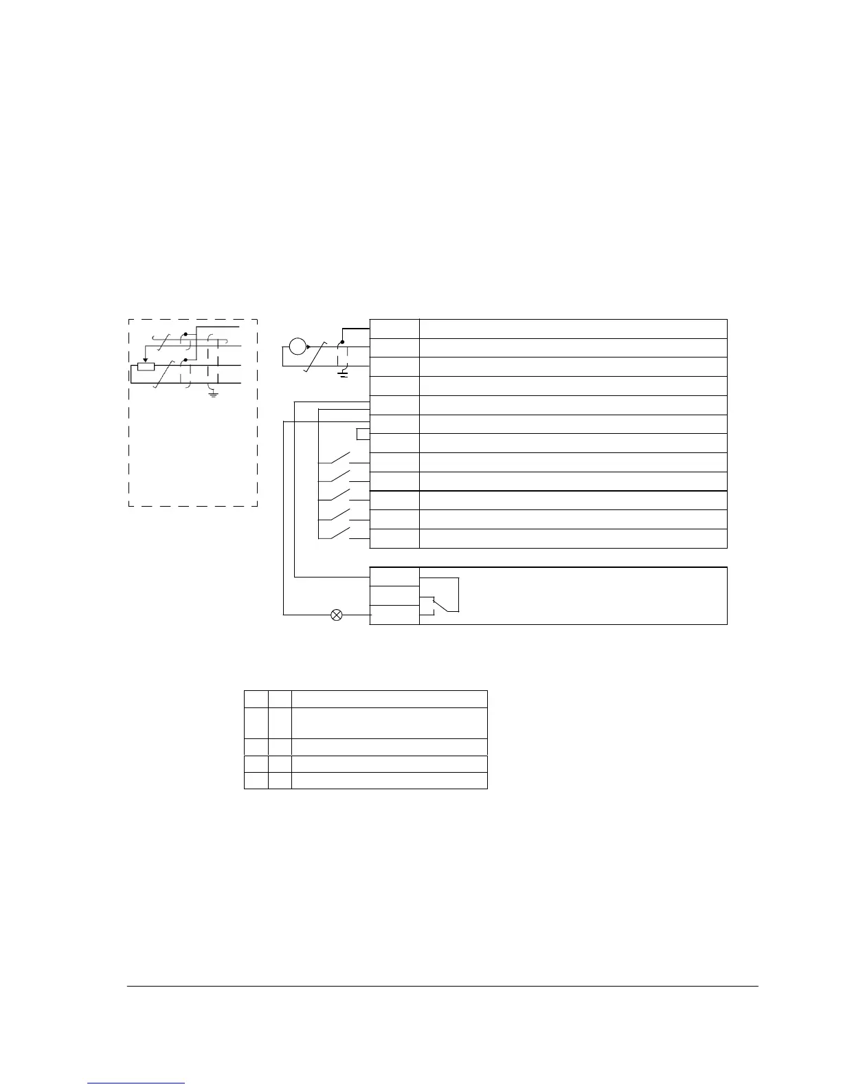
1…10 kohm
Default I/O
connections
3)
I/O connection
4)
SCR Signal cable shield (screen)
AI Frequency reference: 0…20 mA
GND Analog input circuit common
+10V Reference voltage: +10 V DC, max. 10 mA
Alternative connection
for AI1. If used, switch
IU selector to U
(0…10 V voltage
signal).
+24V Auxiliary voltage output: +24 V DC, max. 200 mA
GND Auxiliary voltage output common
COM Digital input common
DI1 Start forward: If DI1 = DI2, the drive stops.
DI2 Start reverse
DI3 Constant speed selection
1)
DI4 Constant speed selection
1)
DI5 Acceleration and deceleration selection
2)
Relay connection
5)
COM Relay output
NC
No fault [Fault (-1)]
NO
1)
See parameter group 12 CONSTANT SPEEDS:
2)
0 = ramp times according to parameters 2202
ACCELER TIME 1 and 2203 DECELER
TIME 1.
1 = ramp times according to parameters 2205
ACCELER TIME 2 and 2206 DECELER
TIME 2.
3)
360 degree grounding under a clamp.
4)
Tightening torque: 0.22 N·m / 2 lbf·in
5)
Tightening torque: 0.5 N·m / 4.4 lbf·in

 Loading...


