Actual signals and parameters
Parameters in the Long parameter mode
Displays the drive current and voltage ratings.
Value in format XXXY hex:
XXX = Nominal current of the drive in amperes. An “A” indicates decimal
point. For example if XXX is 8A8, nominal current is 8.8 A.
Y = Nominal voltage of the drive:
1 = 1-phase 200…240 V
2 = 3-phase 200…240 V
4 = 3-phase 380…480 V
Selection of actual signals to be displayed on the panel
Selects the first signal to be displayed on the control panel in the Output
mode.
3401
3404
3405
LOC
49
.
1
Hz
OUTPUT FWD
Parameter index in group 01 OPERATING DATA. For example, 102 = 0102
SPEED. If value is set to 0, no signal is selected.
If parameter 3401 SIGNAL1 PARAM, 3408 SIGNAL2 PARAM and 3415
SIGNAL3 PARAM values are all set to 0, n.A. is displayed.
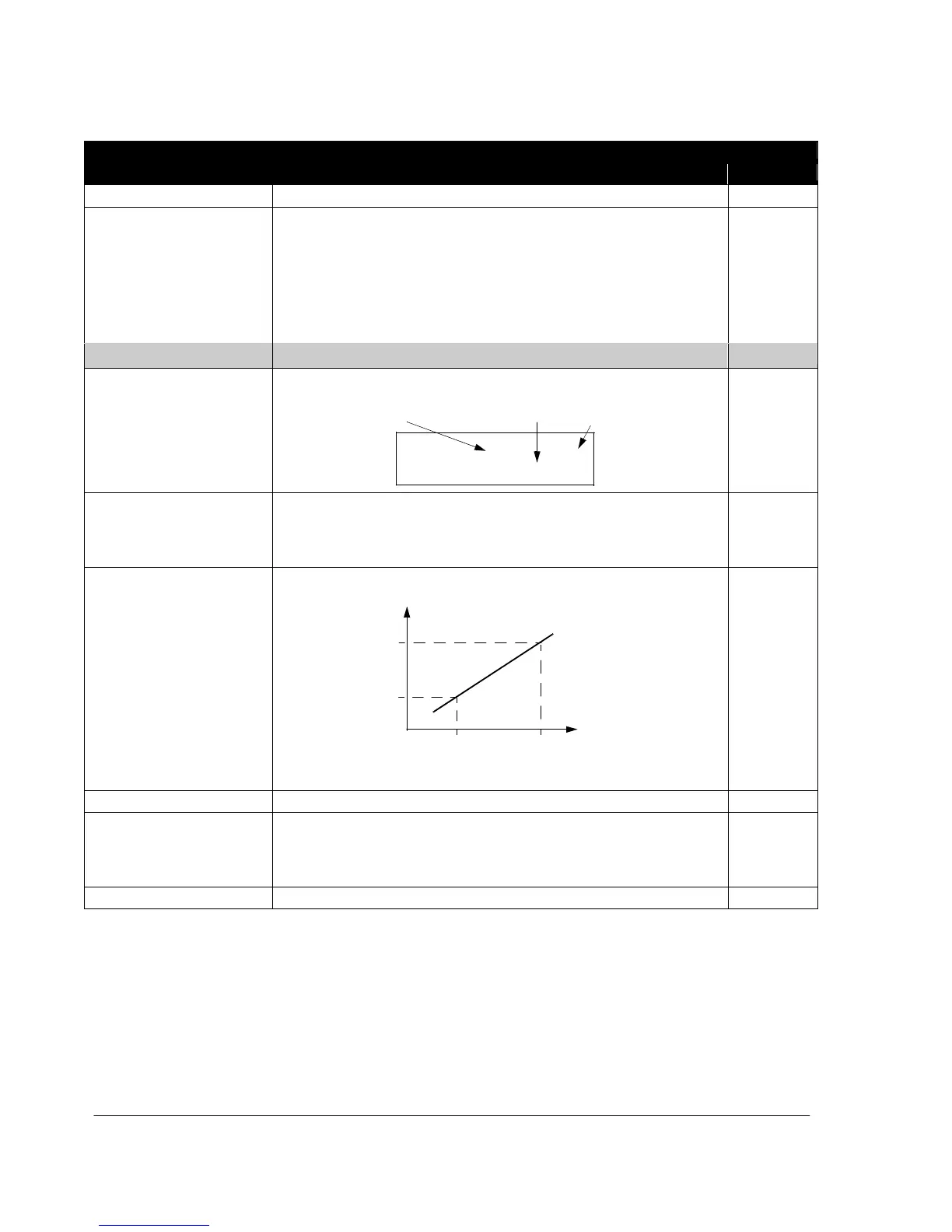
Defines the minimum value for the signal selected by parameter 3401
SIGNAL1 PARAM.
Display
value
3407
3406
Source value
3402 3403
Note: Parameter is not effective if parameter 3404 OUTPUT1 DSP FORM
setting is 9 (DIRECT).
Setting range depends on parameter 3401 SIGNAL1 PARAM setting.
Defines the maximum value for the signal selected by parameter 3401
SIGNAL1 PARAM. See the figure for parameter 3402 SIGNAL1 MIN.
Note: Parameter is not effective if parameter 3404 OUTPUT1 DSP FORM
setting is 9 (DIRECT).
Setting range depends on parameter 3401 SIGNAL1 PARAM setting.

 Loading...


