Start-up and control with I/O
How to control the drive through the I/O interface
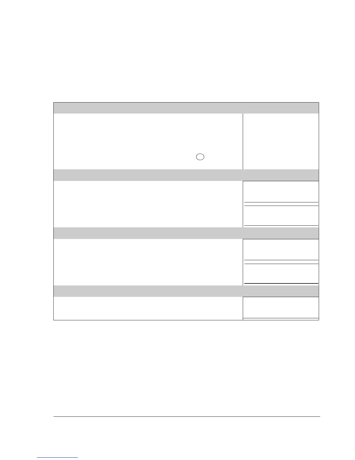
The table below instructs how to operate the drive through the digital and analog
inputs when:
• the motor start-up is performed, and
• the default (standard) parameter settings are valid.
If you need to change the direction of rotation, check that parameter
1003 DIRECTION is set to 3 (REQUEST).
Ensure that the control connections are wired according to the
connection diagram given for the ABB standard macro.
Ensure that the drive is in remote control. Press key
LOC
to switch
REM
between remote and local control.
See Default I/O connection
diagram on page 46.
In remote control, the panel
display shows text REM.
STARTING AND CONTROLLING THE SPEED OF THE MOTOR
Start by switching digital input DI1 on.
Text FWD starts flashing fast and stops after the setpoint is reached.
Regulate the drive output frequency (motor speed) by adjusting the
voltage or current of the analog input AI(1).
REM
0
.
0
Hz
OUTPUT FWD
REM
50
.
0
Hz
OUTPUT FWD
CHANGING THE DIRECTION OF THE MOTOR ROTATION
Reverse direction: Switch digital input DI2 on.
Forward direction: Switch digital input DI2 off.
REM
50
.
0
Hz
OUTPUT REV
REM
50
.
0
Hz
OUTPUT FWD
Switch digital input DI1 off.
The motor stops and text FWD starts flashing slowly.