EasyManua.ls Logo

ABB ACS150 series User Manual

ABB ACS150 series
173 pages
To Next Page IconTo Next Page
To Previous Page IconTo Previous Page
Page #164 background imageLoading...
Page #164 background image
161
Appendix: Process PID control
What this chapter contains
The chapter contains instructions on quick configuration of the process control, gives
an application example and describes the PID sleep functionality.
Process PID control
There is a built-in PID controller in the drive. The controller can be used to control
process variables such as pressure, flow or fluid level. In process PID control, a
process reference (setpoint) is set with drive's integrated potentiometer. An actual
value (process feedback) is connected to the drive's analog input. The process PID
control adjusts the drive speed in order to keep the measured process quantity
(actual value) at the desired level (setpoint).
Quick configuration of process PID control
9902 APPLIC
1
MACRO
4010 SET
2
POINT SEL
Process
PID
4018 ACT1
MINUMUM
4016 ACT1
3
INPUT
4019 ACT1 MAXIMUM
4019 AC
T1
MAXIMUM
4017 ACT2
4
INPUT
4018 ACT1 MINIMUM
4021 ACT2 MAXIMUM
4020 ACT2 MINUMUM
4001 GAIN
4014 FBK
SEL
PID output
6
4002 INTEGRATION
TI
ME
5
4003 DERIVATION
TIME
4005 ERROR VALUE
INV
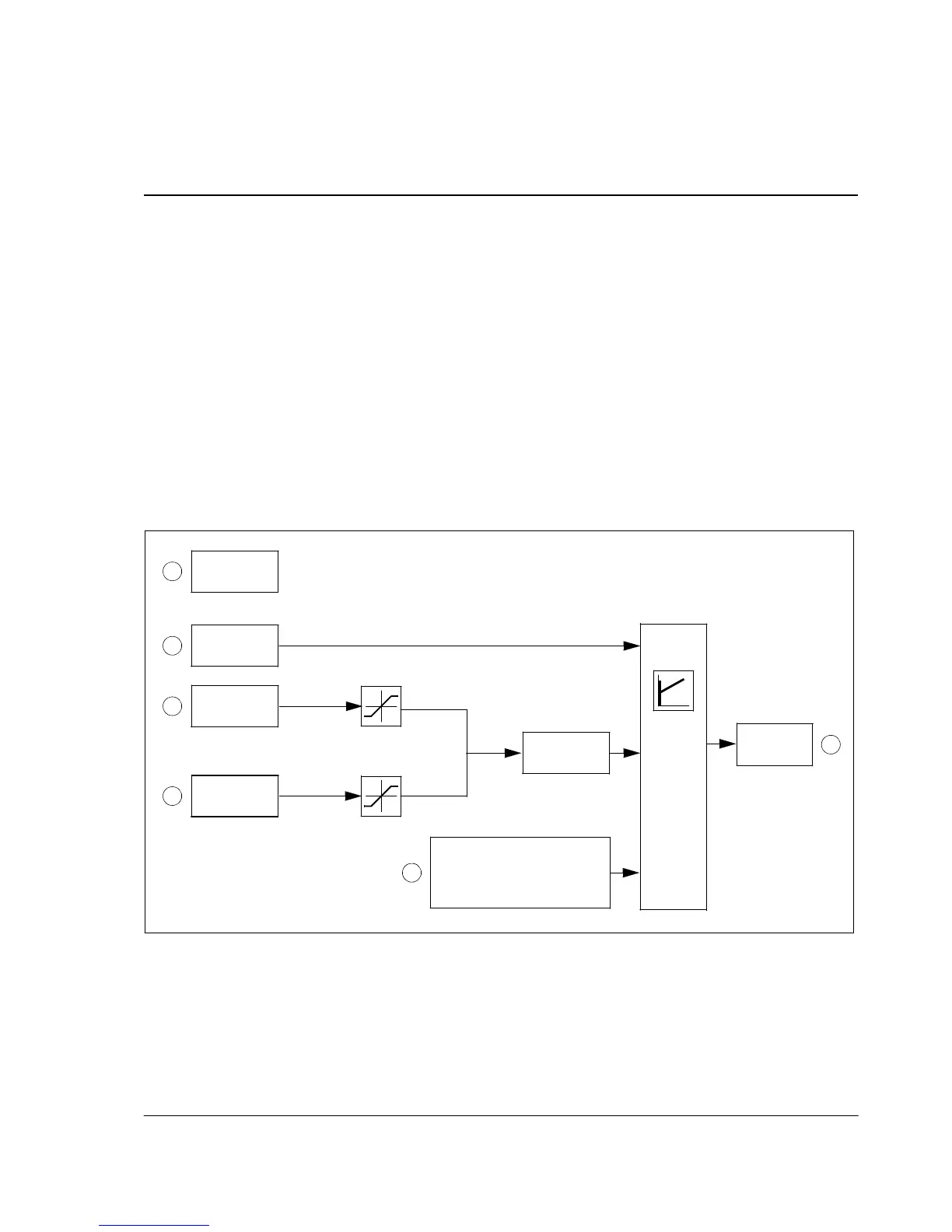
1. 9902 APPLIC MACRO: Set 9902 APPLICATION MACRO to 6 (PID CONTROL).
2. 4010 SET POINT SEL: Determine the source for the PID reference signal (PID
setpoint) and define its scale (4006 UNITS, 4007 UNIT SCALE).
3. 4014 FBK SEL and 4016 ACT1 INPUT: Select the process actual value
(feedback signal) for the system and configure feedback levels (4018 ACT1
MINUMUM, 4019 ACT1 MAXIMUM).

Table of Contents

Question and Answer IconNeed help?

Do you have a question about the ABB ACS150 series and is the answer not in the manual?

ABB ACS150 series Specifications

General IconGeneral
Power Range0.37 to 4 kW
Frequency Range0 to 500 Hz
Protection ClassIP20
Overload Capacity150% for 60 seconds
Braking ChopperBuilt-in
Control MethodScalar control
Supply Voltage200-240 V (1-phase), 200-480 V (3-phase)
EMC FilterBuilt-in
Input Voltage200-240 V (1-phase), 200-480 V (3-phase)
Protection FeaturesOvervoltage, undervoltage, overcurrent, short-circuit
Communication OptionsModbus RTU
Voltage Range200 to 240 V (1-phase), 380 to 480 V (3-phase)

Summary

Safety

Electrical Safety

Instructions for safe electrical installation and maintenance procedures.

General Safety

General safety precautions to avoid physical injury or equipment damage.

Operation Principle and Hardware Description

Power Connections and Control Interfaces

Diagram and explanation of how to connect power and control cables to the drive.

Planning the Electrical Installation

Electrical Installation

Connecting the Power Cables

Detailed instructions and diagrams for connecting power cables.

Connecting the Control Cables

Instructions for connecting various control signals and I/O.

Start-up and Control with I/O

How to Start up the Drive

Step-by-step guide for the initial start-up procedure of the drive.

How to Control the Drive Through the I/O Interface

Instructions on operating the drive using digital and analog I/O signals.

Control Panel

Operation

How to use the control panel for various operations like starting, stopping, and setting parameters.

How to Start, Stop and Switch Between Local and Remote Control

Detailed steps for managing drive control modes.

How to Set the Frequency Reference

Procedures for setting the desired motor speed reference.

How to Select a Parameter and Change its Value

Step-by-step guide for navigating and modifying parameter values.

Application Macros

Actual Signals and Parameters

Actual Signals

Description of various real-time signals that can be monitored from the drive.

Parameters in the Long Parameter Mode

Comprehensive list and description of all drive parameters.

10 START/STOP/DIR

Defines sources for external start, stop, and direction commands.

30 FAULT FUNCTIONS

Configuration of programmable protection functions for the drive.

31 AUTOMATIC RESET

Settings for automatically resetting faults after detection.

40 PROCESS PID SET 1

Parameter set for configuring the drive's built-in PID controller.

Fault Tracing

Alarm Messages Generated by the Drive

List of common alarm codes, their causes, and recommended actions.

Fault Messages Generated by the Drive

List of common fault codes, their causes, and recommended actions.

Maintenance

Technical Data

Ratings

Electrical and performance ratings of the drive, including current and power.

Appendix: Process PID Control

How to Scale the PID Actual (Feedback) Signal 0…10 bar / 4…20 mA

Guide on scaling the analog feedback signal for PID control.

Related product manuals