EasyManua.ls Logo

ABB ACS150 series User Manual

ABB ACS150 series
173 pages
To Next Page IconTo Next Page
To Previous Page IconTo Previous Page
Page #120 background imageLoading...
Page #120 background image
Actual signals and parameters
119
Parameters in the Long parameter mode
Index
Name/Selection
Description
Def
3421 OUTPUT3 MAX
Sets the maximum display value for the signal selected by parameter 3415
SIGNAL3 PARAM. See parameter 3402 SIGNAL1 MIN.
-
x…x
Setting range depends on parameter 3415 SIGNAL3 PARAM setting.
-
40 PROCESS PID SET 1
Process PID (PID1) control parameter set 1.
4001 GAIN
Defines the gain for the process PID controller. High gain may cause speed
oscillation.
1.0
0.1100.0
Gain. When value is set to 0.1, the PID controller output changes one-tenth
as much as the error value. When value is set to 100, the PID controller
output changes one hundred times as much as the error value.
4002 INTEGRATION TIME
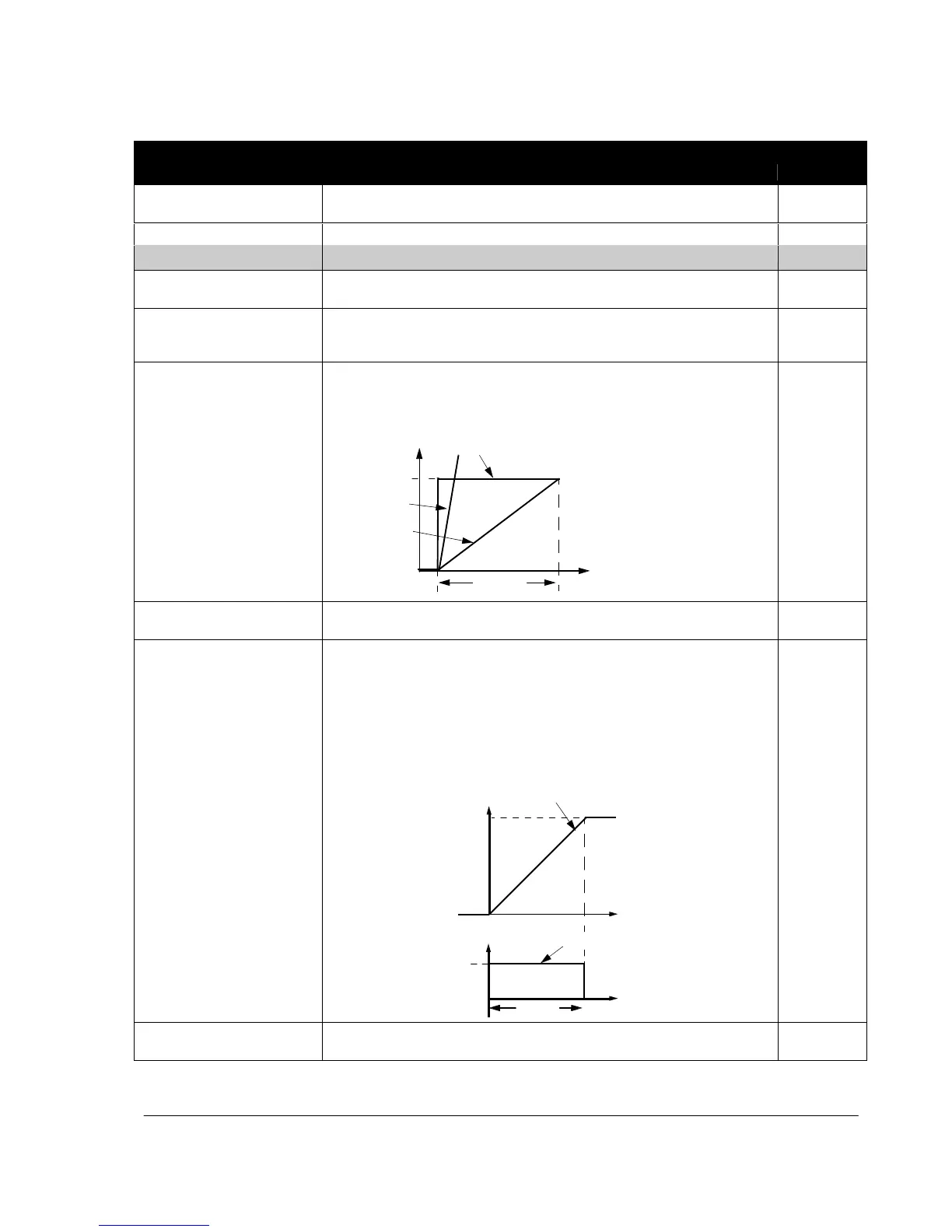
Defines the integration time for the process PID1 controller. The integration
time defines the rate at which the controller output changes when the error
value is constant. The shorter the integration time, the faster the continuous
error value is corrected. Too short an integration time makes the control
unstable.
A
A = Error
B
B = Error value step
C = Controller output with gain = 1
D (4001 = 10)
D = Controller output with gain = 10
C (4001 = 1)
t
4002
60.0 s
0.03600.0 s
Integration time. If parameter value is set to zero, integration (I-part of the
PID controller) is disabled.
4003 DERIVATION TIME
Defines the derivation time for the process PID controller. Derivative action
boosts the controller output if the error value changes. The longer the
derivation time, the more the speed controller output is boosted during the
change. If the derivation time is set to zero, the controller works as a PI
controller, otherwise as a PID controller.
The derivation makes the control more responsive for disturbances.
The derivative is filtered with a 1-pole filter. Filter time constant is defined by
parameter 4004 PID DERIV FILTER.
Error
Process error value
100%
0%
t
PID output
D-part of controller ou
tput
Gain
4001
4003
0.0 s
0.010.0 s
Derivation time. If parameter value is set to zero, the derivative part of the
PID controller is disabled.

Table of Contents

Question and Answer IconNeed help?

Do you have a question about the ABB ACS150 series and is the answer not in the manual?

ABB ACS150 series Specifications

General IconGeneral
Power Range0.37 to 4 kW
Frequency Range0 to 500 Hz
Protection ClassIP20
Overload Capacity150% for 60 seconds
Braking ChopperBuilt-in
Control MethodScalar control
Supply Voltage200-240 V (1-phase), 200-480 V (3-phase)
EMC FilterBuilt-in
Input Voltage200-240 V (1-phase), 200-480 V (3-phase)
Protection FeaturesOvervoltage, undervoltage, overcurrent, short-circuit
Communication OptionsModbus RTU
Voltage Range200 to 240 V (1-phase), 380 to 480 V (3-phase)

Summary

Safety

Electrical Safety

Instructions for safe electrical installation and maintenance procedures.

General Safety

General safety precautions to avoid physical injury or equipment damage.

Operation Principle and Hardware Description

Power Connections and Control Interfaces

Diagram and explanation of how to connect power and control cables to the drive.

Planning the Electrical Installation

Electrical Installation

Connecting the Power Cables

Detailed instructions and diagrams for connecting power cables.

Connecting the Control Cables

Instructions for connecting various control signals and I/O.

Start-up and Control with I/O

How to Start up the Drive

Step-by-step guide for the initial start-up procedure of the drive.

How to Control the Drive Through the I/O Interface

Instructions on operating the drive using digital and analog I/O signals.

Control Panel

Operation

How to use the control panel for various operations like starting, stopping, and setting parameters.

How to Start, Stop and Switch Between Local and Remote Control

Detailed steps for managing drive control modes.

How to Set the Frequency Reference

Procedures for setting the desired motor speed reference.

How to Select a Parameter and Change its Value

Step-by-step guide for navigating and modifying parameter values.

Application Macros

Actual Signals and Parameters

Actual Signals

Description of various real-time signals that can be monitored from the drive.

Parameters in the Long Parameter Mode

Comprehensive list and description of all drive parameters.

10 START/STOP/DIR

Defines sources for external start, stop, and direction commands.

30 FAULT FUNCTIONS

Configuration of programmable protection functions for the drive.

31 AUTOMATIC RESET

Settings for automatically resetting faults after detection.

40 PROCESS PID SET 1

Parameter set for configuring the drive's built-in PID controller.

Fault Tracing

Alarm Messages Generated by the Drive

List of common alarm codes, their causes, and recommended actions.

Fault Messages Generated by the Drive

List of common fault codes, their causes, and recommended actions.

Maintenance

Technical Data

Ratings

Electrical and performance ratings of the drive, including current and power.

Appendix: Process PID Control

How to Scale the PID Actual (Feedback) Signal 0…10 bar / 4…20 mA

Guide on scaling the analog feedback signal for PID control.

Related product manuals