Actual signals and parameters
Parameters in the Long parameter mode
Defines the filter time constant for the derivative part of the process PID
controller. Increasing the filter time smooths the derivative and reduces
noise.
Filter time constant. If parameter value is set to zero, the derivative filter is
disabled.
Selects the relationship between the feedback signal and drive speed (drive
output frequency).
Normal: A decrease in feedback signal increases drive speed (drive output
frequency). Error = Ref - Fbk
Inverted: A decrease in feedback signal decreases drive speed (drive output
frequency). Error = Fbk - Ref
Selects the unit for PID controller actual values.
See parameter 3405 OUTPUT1 UNIT selections 0…12 (NO UNIT…mV).
Defines the decimal point location for the display parameter selected by
parameter 4006 UNITS.
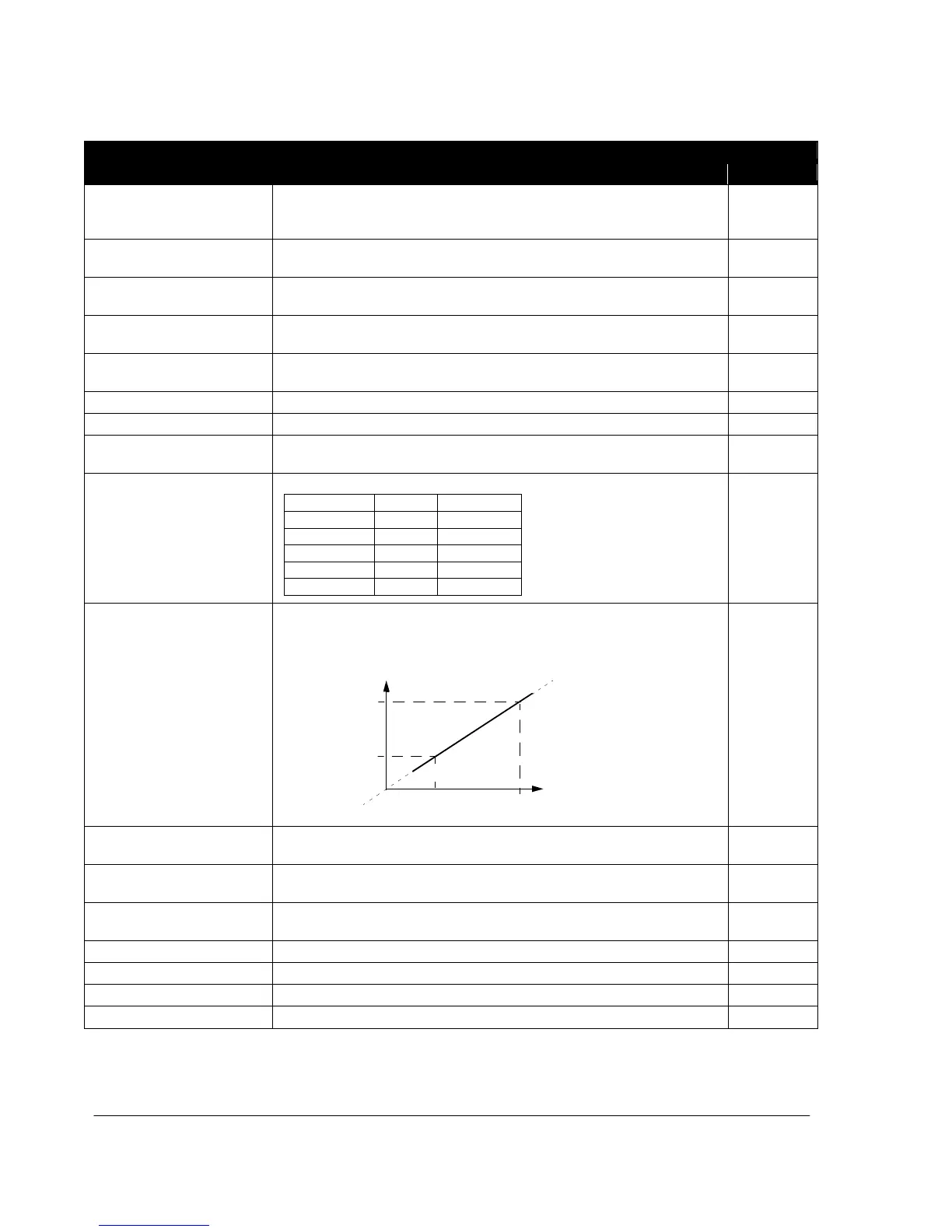
Defines together with parameter 4009 100% VALUE the scaling applied to
the PID controller’s actual values.
Units (4006)
Scale (4007)
+1000%
4009
4008
Internal scale (%)
0% 100%
-1000%
Unit and range depend on the unit and scale defined by parameters 4006
UNITS and 4007 UNIT SCALE.
Defines together with parameter 4008 0% VALUE the scaling applied to the
PID controller’s actual values.
Unit and range depend on the unit and scale defined by parameters 4006
UNITS and 4007 UNIT SCALE.
Selects the source for the process PID controller reference signal.

 Loading...


