EasyManua.ls Logo

ABB ACS150 series User Manual

ABB ACS150 series
173 pages
To Next Page IconTo Next Page
To Previous Page IconTo Previous Page
Page #76 background imageLoading...
Page #76 background image
75
Application macros
Hand/Auto macro
This macro can be used when switching between two external control devices is
needed. To enable the macro, set the value of parameter 9902 APPLIC MACRO to
5 (HAND/AUTO).
For the parameter default values, see section Default parameter values with different
macros on page 79. If you use other than the default connections presented below,
see section I/O terminals on page 44.
Note: Parameter 2108 START INHIBIT must remain in the default setting 0 (OFF).
1…10 kohm
Default I/O
connections
2)
I/O connection
3)
SCR Signal cable shield (screen)
AI Frequency reference (Auto): 4…20 mA
1)
GND Analog input circuit common
+10V Reference voltage: +10 V DC, max. 10 mA
Alternative connection
for AI1. If used, switch
IU selector to U
(2…10 V voltage
signal).
+24V Auxiliary voltage output: +24 V DC, max. 200 mA
GND Auxiliary voltage output common
COM Digital input common
DI1 Stop (0) / Start (1) (Hand)
DI2 Forward (0) / Reverse (1) (Hand)
DI3 Hand (0) / Auto (1) control selection
DI4 Forward (0) / Reverse (1) (Auto)
DI5 Stop (0) / Start (1) (Auto)
Relay connection
4)
COM Relay output
NC
No fault [Fault (-1)]
NO
1)
In the Hand mode, the frequency reference
comes from the integrated potentiometer.
2)
360 degree grounding under a clamp.
3)
Tightening torque: 0.22 N·m / 2 lbf·in
4)
Tightening torque: 0.5 N·m / 4.4 lbf·in

Table of Contents

Question and Answer IconNeed help?

Do you have a question about the ABB ACS150 series and is the answer not in the manual?

ABB ACS150 series Specifications

General IconGeneral
Power Range0.37 to 4 kW
Frequency Range0 to 500 Hz
Protection ClassIP20
Overload Capacity150% for 60 seconds
Braking ChopperBuilt-in
Control MethodScalar control
Supply Voltage200-240 V (1-phase), 200-480 V (3-phase)
EMC FilterBuilt-in
Input Voltage200-240 V (1-phase), 200-480 V (3-phase)
Protection FeaturesOvervoltage, undervoltage, overcurrent, short-circuit
Communication OptionsModbus RTU
Voltage Range200 to 240 V (1-phase), 380 to 480 V (3-phase)

Summary

Safety

Electrical Safety

Instructions for safe electrical installation and maintenance procedures.

General Safety

General safety precautions to avoid physical injury or equipment damage.

Operation Principle and Hardware Description

Power Connections and Control Interfaces

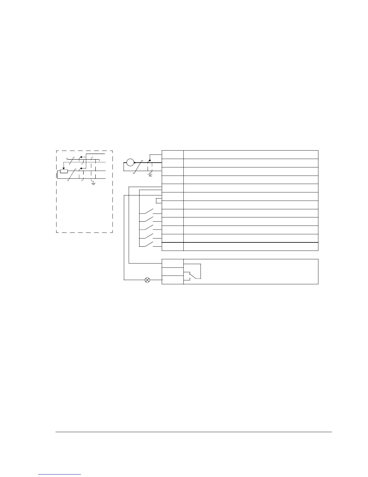
Diagram and explanation of how to connect power and control cables to the drive.

Planning the Electrical Installation

Electrical Installation

Connecting the Power Cables

Detailed instructions and diagrams for connecting power cables.

Connecting the Control Cables

Instructions for connecting various control signals and I/O.

Start-up and Control with I/O

How to Start up the Drive

Step-by-step guide for the initial start-up procedure of the drive.

How to Control the Drive Through the I/O Interface

Instructions on operating the drive using digital and analog I/O signals.

Control Panel

Operation

How to use the control panel for various operations like starting, stopping, and setting parameters.

How to Start, Stop and Switch Between Local and Remote Control

Detailed steps for managing drive control modes.

How to Set the Frequency Reference

Procedures for setting the desired motor speed reference.

How to Select a Parameter and Change its Value

Step-by-step guide for navigating and modifying parameter values.

Application Macros

Actual Signals and Parameters

Actual Signals

Description of various real-time signals that can be monitored from the drive.

Parameters in the Long Parameter Mode

Comprehensive list and description of all drive parameters.

10 START/STOP/DIR

Defines sources for external start, stop, and direction commands.

30 FAULT FUNCTIONS

Configuration of programmable protection functions for the drive.

31 AUTOMATIC RESET

Settings for automatically resetting faults after detection.

40 PROCESS PID SET 1

Parameter set for configuring the drive's built-in PID controller.

Fault Tracing

Alarm Messages Generated by the Drive

List of common alarm codes, their causes, and recommended actions.

Fault Messages Generated by the Drive

List of common fault codes, their causes, and recommended actions.

Maintenance

Technical Data

Ratings

Electrical and performance ratings of the drive, including current and power.

Appendix: Process PID Control

How to Scale the PID Actual (Feedback) Signal 0…10 bar / 4…20 mA

Guide on scaling the analog feedback signal for PID control.

Related product manuals