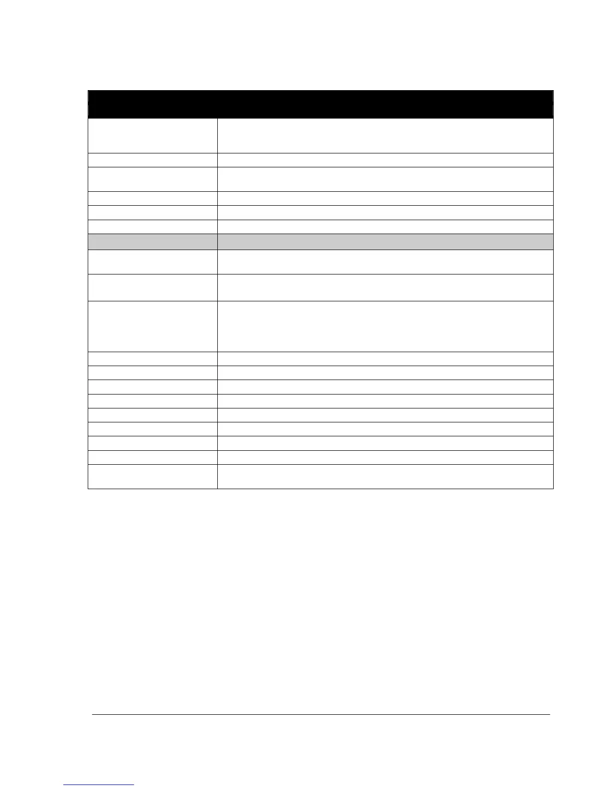
Actual signals and parameters
Motor revolution counter (millions of revolutions). The counter can be reset by pressing
the UP and DOWN keys simultaneously when the control panel is in the Parameter
mode.
Drive control board power-on time in days. Counter cannot be reset.
Drive control board power-on time in 2 second ticks (30 ticks = 60 seconds). Counter
cannot be reset.
Status of digital inputs. Example: 10000 = DI1 is on, DI2...DI5 are off.
Value of frequency input in Hz
Status of relay output. 1 = RO is energized, 0 = RO is de-energized.
Fault history (read-only)
Fault code of the latest fault. See chapter Fault tracing on page 127 for the codes. 0 =
fault history is clear (on panel display = NO RECORD).
Day on which the latest fault occurred.
Format: The number of days elapsed after power-on.
Time at which the latest fault occurred.
Format: Time elapsed after power-on in 2 second ticks (minus the whole days stated by
signal 0402 FAULT TIME 1). 30 ticks = 60 seconds.
For example, value 514 equals 17 minutes and 8 seconds (= 514/30).
Motor speed in rpm at the time the latest fault occurred
Frequency in Hz at the time the latest fault occurred
Intemediate circuit voltage in V DC at the time the latest fault occurred
Motor current in A at the time the latest fault occurred
Motor torque in percent of the motor nominal torque at the time the latest fault occurred
Drive status in hexadecimal format at the time the latest fault occurred
Fault code of the 2nd latest fault. See chapter Fault tracing on page 127 for the codes.
Fault code of the 3rd latest fault. See chapter Fault tracing on page 127 for the codes.
Status of digital inputs DI1…5 at the time the latest fault occurred. Example: 10000 = DI1
is on, DI2...DI5 are off.

 Loading...


