NOTE:
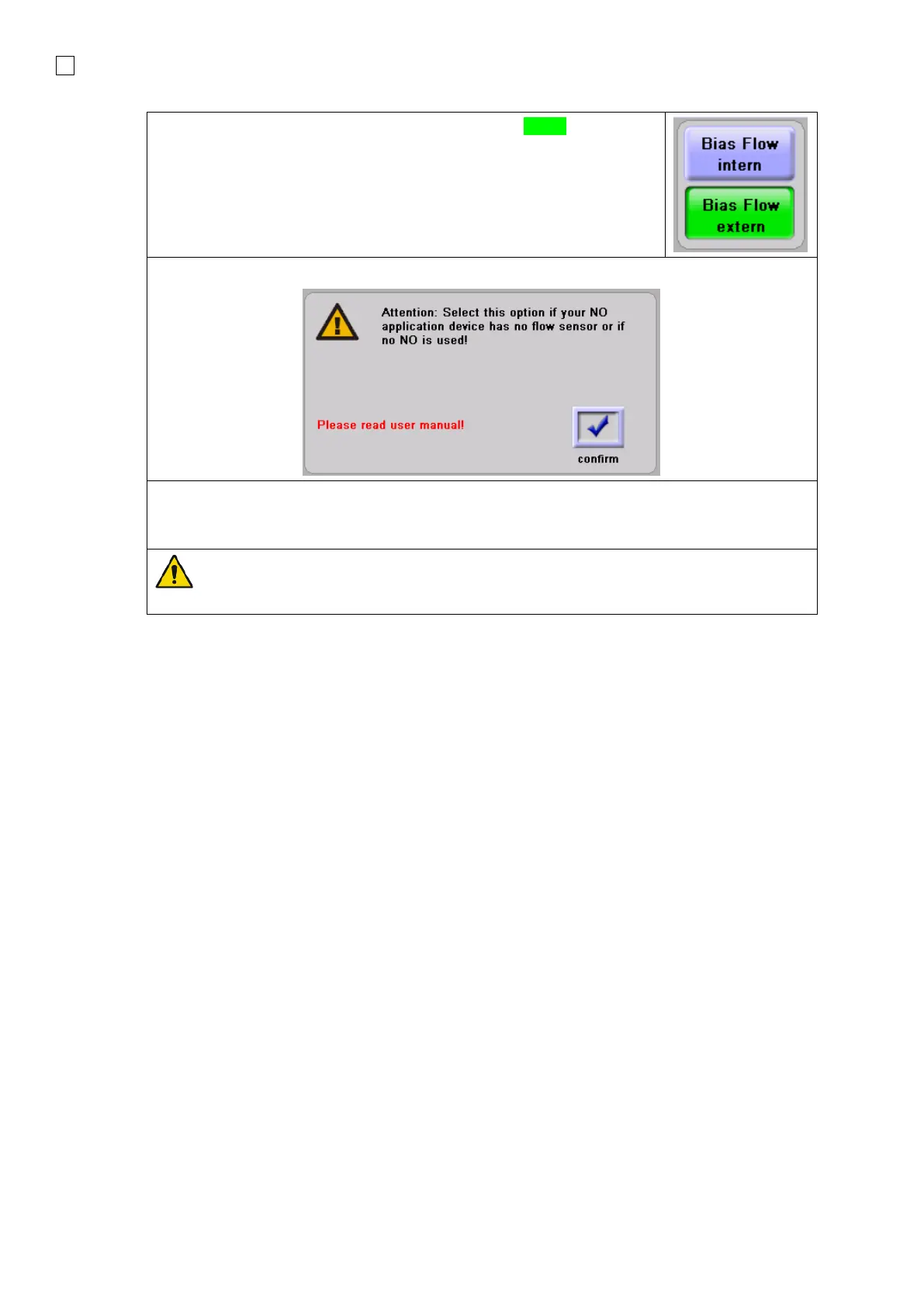
When switching between HFO to a Conventional Ventilation mode, the External NO Flow
sensor can be left in this position.
5.2 Patient circuit assembly
We recommend the use of “Single Use Patient Circuits” to be used on the device. Best performance
is achieved with dual limb heated systems.
Refer to following diagram for setup:
1. Connect the machine end of the Inspiratory limb to the ispiration port (Insp) on the ventilator.
1.1. Connect proximal end of the Inspiratory limb to the humidifier chamber inlet.
2. Connect the machine end of the heated Inspiratory limb to the humidifier chamber outlet.
2.1. Connect the proximal end of the heated Inspiratory limb to the patient connection wye.
3. Connect the distal end of the Expiratory limb to the air filter and then connect them to the
expiration port (Exp) on the ventilator.
3.1. Connect the proximal end of the Expiratory limb to the patient connection wye.
4. Connect the proximal end of the Proximal Pressure tubing to the patient connection wye
monitoring port.
4.1. Connect the machine end of the Proximal Pressure tubing to the Proximal Pressure port
(Prox) on the ventilator.
5. Connect the Inspiratory and Expiratory limb heater connectors with the corresponding
connectors on the humidifier chamber heater base.
 Loading...