RS-232 Data Frame Format
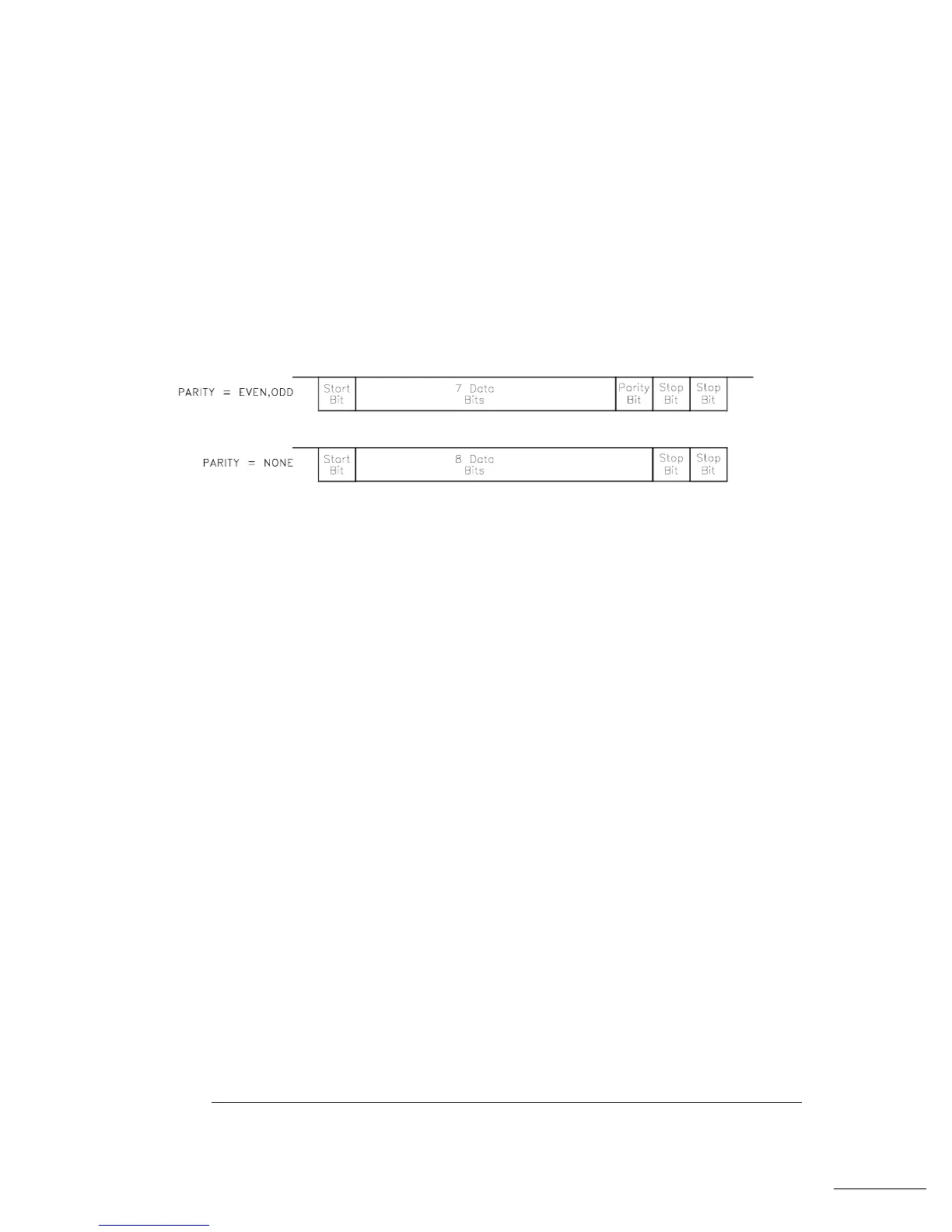
A character frame consists of all the transmitted bits that make up a
single character. The frame is defined as the characters from the start bit
to the last stop bit, inclusively. Within the frame, you can select the
baud rate, number of data bits, and parity type. The function generator
uses the following frame formats for seven and eight data bits.
Connection to a Computer or Terminal
To connect the function generator to a computer or terminal, you must
have the proper interface cable. Most computers and terminals are
DTE
(Data Terminal Equipment) devices. Since the function generator is also
a
DTE device, you must use a DTE-to-DTE interface cable. These cables
are also called null-modem, modem-eliminator, or crossover cables.
The interface cable must also have the proper connector on each end
and the internal wiring must be correct. Connectors typically have
9 pins (
DB-9 connector) or 25 pins (DB-25 connector) with a “male”
or “female” pin configuration. A male connector has pins inside the
connector shell and a female connector has holes inside the connector shell.
If you cannot find the correct cable for your configuration, you may
have to use a wiring adapter. If you are using a
DTE-to-DTE cable, make
sure the adapter is a “straight-through” type. Typical adapters include
gender changers, null-modem adapters, and
DB-9 to DB-25 adapters.
Refer to the cable and adapter diagrams on the following page to
connect the function generator to most computers or terminals. If your
configuration is different than those described, order the 34399A
Adapter Kit. This kit contains adapters for connection to other
computers, terminals, and modems. Instructions and pin diagrams are
included with the adapter kit.
Chapter 4 Remote Interface Reference
RS-232 Interface Configuration
196

 Loading...


