EasyManua.ls Logo

Agilent Technologies 33120A User Manual

Agilent Technologies 33120A
312 pages
To Next Page IconTo Next Page
To Previous Page IconTo Previous Page
Page #23 background image
To set a dc offset voltage
At power-on, the function generator outputs a sine wave with a dc offset
voltage of 0 volts (into a 50
W termination). The following steps show you
how to change the offset to 1.5 mVdc.
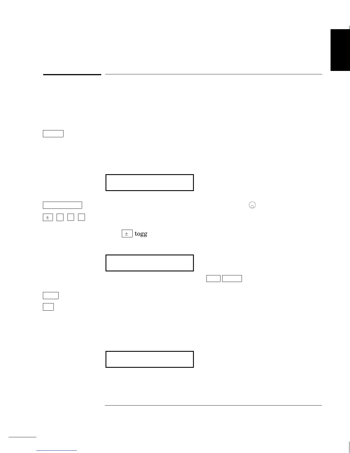
1Enable the offset modify mode.
The displayed offset voltage is either the power-on value or the previous
offset selected. When you change functions, the same offset is used if the
present value is valid for the new function.
+0.000 VDC
2 Enter the magnitude of the desired offset.
1
Notice that the Num annunciator turns on andENTER NUM” flashes
on the display, indicating that the number mode is enabled. Notice
that
toggles the displayed value between + and .
-1.5
To cancel the number mode, press
Shift Cancel .
3 Set the units to the desired value.
At this point, the function generator outputs the waveform with the
displayed offset. Notice that the
Offset annunciator turns on, indicating
that the waveform is being output with an offset. The annunciator will
turn on when the offset is any value other than 0 volts. To turn off the
flashing digit, move the cursor to the left of the display using the arrow keys.
-01.50 mVDC
Offset
5
Enter Number
.
1
kHz
m Vrms
Shift
¿
1
You can also use the knob and arrow keys to enter a number.
See Front-Panel Number Entry” on page 3 for more information.
1
Chapter 1 Quick Start
To set a dc offset voltage
21

Table of Contents

Other manuals for Agilent Technologies 33120A

Questions and Answers:

Agilent Technologies 33120A Specifications

General IconGeneral
BrandAgilent Technologies
Model33120A
CategoryInverter
LanguageEnglish

Summary

Chapter 1 Quick Start

To prepare the function generator for use

Provides initial steps for setting up the device and verifying its readiness for operation.

If the function generator does not turn on

Offers troubleshooting steps for cases where the instrument fails to power on, addressing power and fuse issues.

To adjust the carrying handle

Details how to manipulate the carrying handle for bench-top viewing positions or for carrying the device.

To set the output frequency

Guides the user through changing the output frequency, including mode enabling and value entry.

To set the output amplitude

Explains the process of adjusting the output amplitude, covering mode enabling, value entry, and unit selection.

To set a dc offset voltage

Describes setting a DC offset voltage, including magnitude entry and unit selection.

To set the duty cycle

Details how to set the duty cycle for square waves, covering function selection and modify mode enabling.

To output a stored arbitrary waveform

Guides on selecting and outputting arbitrary waveforms from memory.

To output a dc voltage

Explains how to output a DC voltage by entering the desired magnitude and setting units.

To store the instrument state

Covers saving the current instrument configuration to non-volatile memory for later recall.

To rack mount the function generator

Provides instructions for installing the function generator in a standard 19-inch rack cabinet.

Chapter 2 Front-Panel Menu Operation

Front-panel menu reference

A listing of front-panel menu commands, their functions, and their organization within the menu structure.

A front-panel menu tutorial

A step-by-step guide to navigating and using the instrument's front-panel menu system.

Messages Displayed During Menu Use

Explains common messages encountered while operating the front-panel menu.

Menu Example 1

Illustrates turning on the menu and enabling automatic power-down state recall.

Menu Example 2

Demonstrates using the recall menu feature to revert settings to factory defaults.

Menu Example 3

Shows how to enter numeric parameter values within the menu system.

To select the output termination

Details how to configure the output termination between 50 ohms and High Z.

To output a modulated waveform

Guides on generating an AM waveform by setting carrier and modulating signal parameters.

To output an FSK waveform

Explains how to generate an FSK waveform by setting frequencies and rate.

To output a burst waveform

Covers setting up a burst waveform, including burst count and enabling burst mode.

To trigger a burst or sweep

Describes triggering mechanisms for bursts and sweeps, covering trigger sources.

Chapter 3 Features and Functions

Output Configuration

Provides comprehensive information on configuring the instrument for waveform output, including function, frequency, amplitude, and termination.

Amplitude Modulation (AM)

Details commands for Amplitude Modulation (AM), including setup, shape, frequency, depth, and source.

Burst Modulation

Covers burst modulation, including modes and parameters like count, rate, and phase.

Frequency-Shift Keying (FSK) Modulation

Explains FSK modulation, including frequencies, rate, source, and state control.

Frequency Sweep

Details the frequency sweep function, including parameters like start/stop frequencies, time, and mode.

Triggering

Explains the triggering mechanisms for bursts and sweeps, covering trigger sources.

Arbitrary Waveforms

Introduces arbitrary waveforms, including built-in types and user-defined capabilities.

System-Related Operations

Covers topics like power-down recall, self-test, error conditions, and display control.

Remote Interface Configuration

Provides information on configuring the remote interface, including GPIB address and interface selection.

Calibration Overview

Gives an overview of calibration features, including security, count, and message recording.

Power-On and Reset State

Details the instrument's state upon power-on or reset, including factory settings.

Chapter 4 Remote Interface Reference

SCPI Command Summary

Summarizes SCPI commands for programming the generator remotely, including conventions and command structure.

Simplified Programming Overview

Introduces basic techniques for programming the generator remotely, covering APPLy and low-level commands.

Output Configuration Commands

Lists low-level SCPI commands for configuring output parameters like function, frequency, and amplitude.

AM Modulation Commands

Details SCPI commands for controlling Amplitude Modulation (AM) parameters.

FM Modulation Commands

Lists SCPI commands for configuring Frequency Modulation (FM) parameters.

Burst Modulation Commands

Provides SCPI commands for controlling burst modulation parameters.

Frequency-Shift Keying (FSK) Commands

Lists SCPI commands for FSK modulation.

Sweep Commands

Details SCPI commands for controlling frequency sweeps.

Arbitrary Waveform Commands

Lists SCPI commands for managing arbitrary waveforms.

Triggering Commands

Covers SCPI commands for controlling trigger sources.

System-Related Commands

Lists SCPI commands for controlling display, beeper, error reporting, and identification.

Calibration Commands

Details SCPI commands for managing calibration, including security and count.

RS-232 Interface Configuration

Explains RS-232 connection, configuration overview, and data frame formats.

The SCPI Status Registers

Explains the SCPI status system, including event and enable registers.

Status Reporting Commands

Lists SCPI commands for reporting status, including error queries.

An Introduction to the SCPI Language

Introduces the SCPI language, its hierarchical structure, and command format conventions.

Halting an Output in Progress

Describes how to stop an output in progress using a device clear message.

To set the GPIB address

Guides on setting the unique GPIB address for the function generator.

To select the remote interface

Explains how to select between GPIB and RS-232 remote interfaces.

To set the baud rate

Details how to select the baud rate for RS-232 communication.

To set the parity

Explains how to set RS-232 parity and data bits.

SCPI Conformance Information

Lists SCPI-approved commands and device-specific commands.

Chapter 5 Error Messages

Execution Errors

Lists and explains error codes related to invalid commands, syntax, parameters, and program mnemonics.

Self-Test Errors

Details errors that indicate failures occurring during the instrument's self-test procedure.

Calibration Errors

Lists errors related to calibration security, code validity, and measurement ranges.

Arbitrary Waveform Errors

Describes errors encountered during arbitrary waveform download and management.

Chapter 6 Application Programs

BASIC Language Programs

Provides example programs written in BASIC for controlling the function generator via GPIB.

C Language Programs

Offers example programs written in C for controlling the generator using the GPIB Interface Card.

QuickBASIC Language Programs

Presents example programs for QuickBASIC, utilizing the GPIB Command Library.

Using the APPLy Command

Demonstrates using the APPLy command in BASIC and C for setting up waveforms and triggers.

Using the Low-Level Commands

Shows how to use low-level SCPI commands for AM waveform setup and instrument state storage.

Downloading an Arbitrary Waveform over GPIB

Teaches defining and downloading waveform points via GPIB, and copying to non-volatile memory.

Downloading an Arbitrary Waveform over RS-232

Demonstrates downloading arbitrary waveforms using ASCII and binary data over RS-232.

Using the Status Registers

Explains using Status Registers to generate interrupts for SCPI errors and service them.

Chapter 7 Tutorial

Direct Digital Synthesis

Explains the DDS signal generation technique used by the instrument.

Signal Imperfections

Discusses common signal imperfections like spurious signals, DAC errors, and phase truncation.

Creating Arbitrary Waveforms

Guides on creating arbitrary waveforms, controlling amplitude quantization and phase truncation errors.

Output Amplitude Control

Details how the DAC is used to control output amplitude levels and recommendations for minimizing quantization errors.

Floating Signal Generators

Explains the concept of floating signal generators and methods to eliminate ground loops.

Attributes of AC Signals

Describes attributes of AC signals like sine waves, including RMS, peak, and average values.

Modulation

Explains modulation processes, including AM, FM, Frequency Sweep, FSK, and Burst Modulation.

Chapter 8 Specifications

WAVEFORMS

Lists standard and arbitrary waveform types, their lengths, resolution, sample rate, and memory.

FREQUENCY CHARACTERISTICS

Details frequency ranges, resolution, and accuracy for standard and arbitrary waveforms.

SINEWAVE SPECTRAL PURITY

Provides specifications for harmonic distortion, spurious output, and phase noise for sine waves.

SIGNAL CHARACTERISTICS

Covers characteristics like rise/fall time, overshoot, asymmetry, and duty cycle for square, triangle, and arb waveforms.

OUTPUT CHARACTERISTICS (1)

Specifies output amplitude ranges, accuracy, flatness, offset, impedance, units, isolation, and protection.

MODULATION CHARACTERISTICS

Lists characteristics for AM, FM, Burst, and FSK modulation, including frequency, depth, and source.

SYSTEM CHARACTERISTICS

Provides configuration times for function changes, frequency, amplitude, offset, and arb download times.

REAR-PANEL INPUTS

Details external modulation and trigger/FSK/burst gate input specifications like latency and jitter.

GENERAL SPECIFICATIONS

Covers power supply, frequency, installation, environment, memory, dimensions, weight, safety, EMC, warranty, and accessories.

PRODUCT DIMENSIONS

Provides physical dimensions for bench top and rack mount configurations in millimeters.

Related product manuals