Rockwell Automation Publication 2198-UM002G-EN-P - February 2019 109
Connector Data and Feature Descriptions Chapter 4
Table 46 - Digital Input Specifications
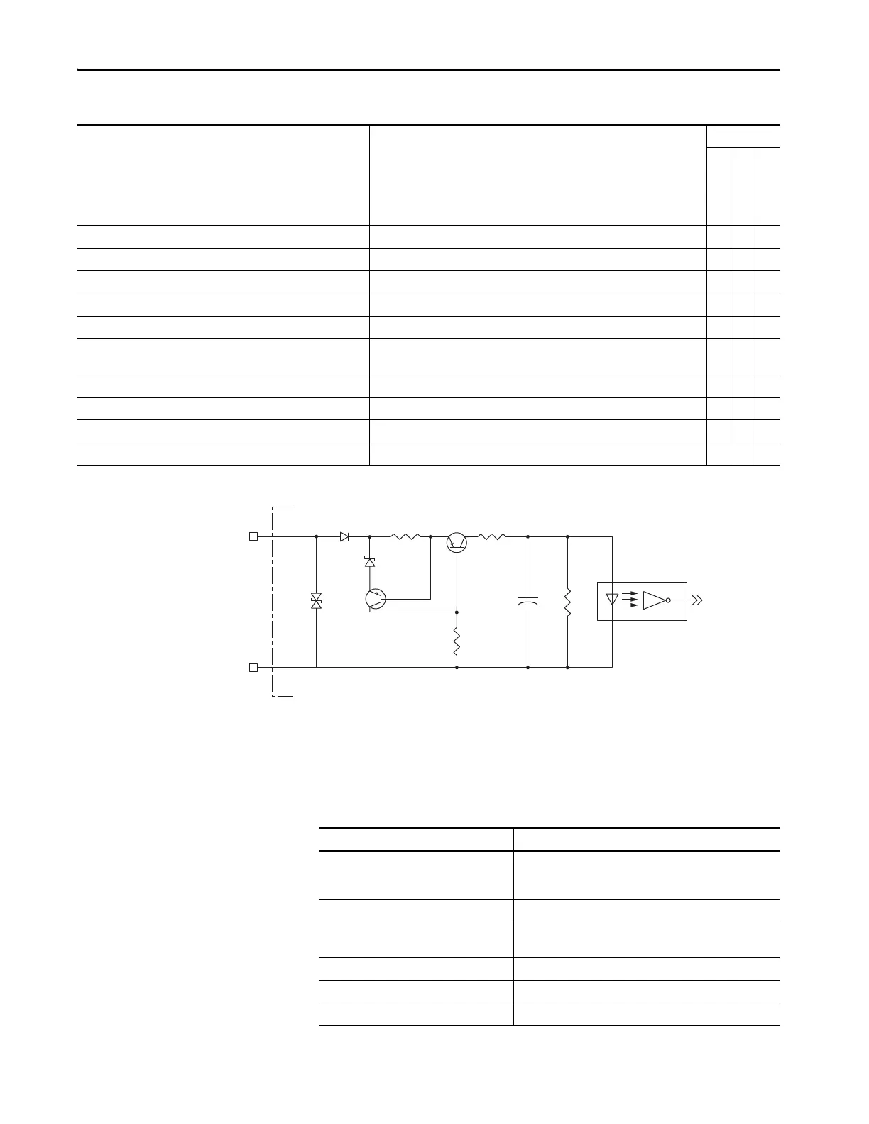
Figure 65 - Digital Input Circuitry
Ethernet Communication Specifications
The PORT1 and PORT2 (RJ45) Ethernet connectors provide
communication with the Logix 5000™ controller.
Attribute Value
Drive Module
2198-Pxxx
2198-xxxx-ERSx
2198-RPxxx
Digital input type Optically isolated, active high, single-ended, current sinking (EN 61131-2 Type 1) X X X
Input current (with 24V applied) 12 mA, typical X X X
On-state input voltage 15…30V @ 15 mA, max X X X
Off-state input voltage -1.0…5.0V X X X
Pulse reject filtering (applies to registration function only) 12.0 μs – X –
Pulse reject filtering (debounce filter)
Applies to all other input functions, Home, for example.
20 ms, nom X X X
Propagation delay (registration functions, inverters only) 0 (delay compensated) – X –
Registration accuracy (inverters only) ±3 μs – X –
Registration repeatability (inverters only) 700 ns – X –
Windowed registration invalid-to-valid event delay (inverters only) 125 μs, min – X –
INPUT
COM
INx
IOD-1 or IOD-3
IOD-2
Kinetix 5700 Drive Module
24V DC
Attribute Value
Communication
The drive auto-negotiates speed and duplex modes. These modes
can be forced through the Logix Designer application. 100BASE-
TX, full duplex is recommended for maximum performance.
Cyclic update period 1.0 ms, min
Embedded switch features
Three-port, cut-through, time correction on IEEE-1588 packets,
limited filtering, quality of service with four priority levels
Auto MDI/MDIX crossover detection/correction Yes
Port-to-port time synchronization variation 100 ns, max
Cabling CAT5e shielded, 100 m (328 ft) max

 Loading...


