Rockwell Automation Publication 2198-UM002G-EN-P - February 2019 155
Connect the Kinetix 5700 Drive System Chapter 5
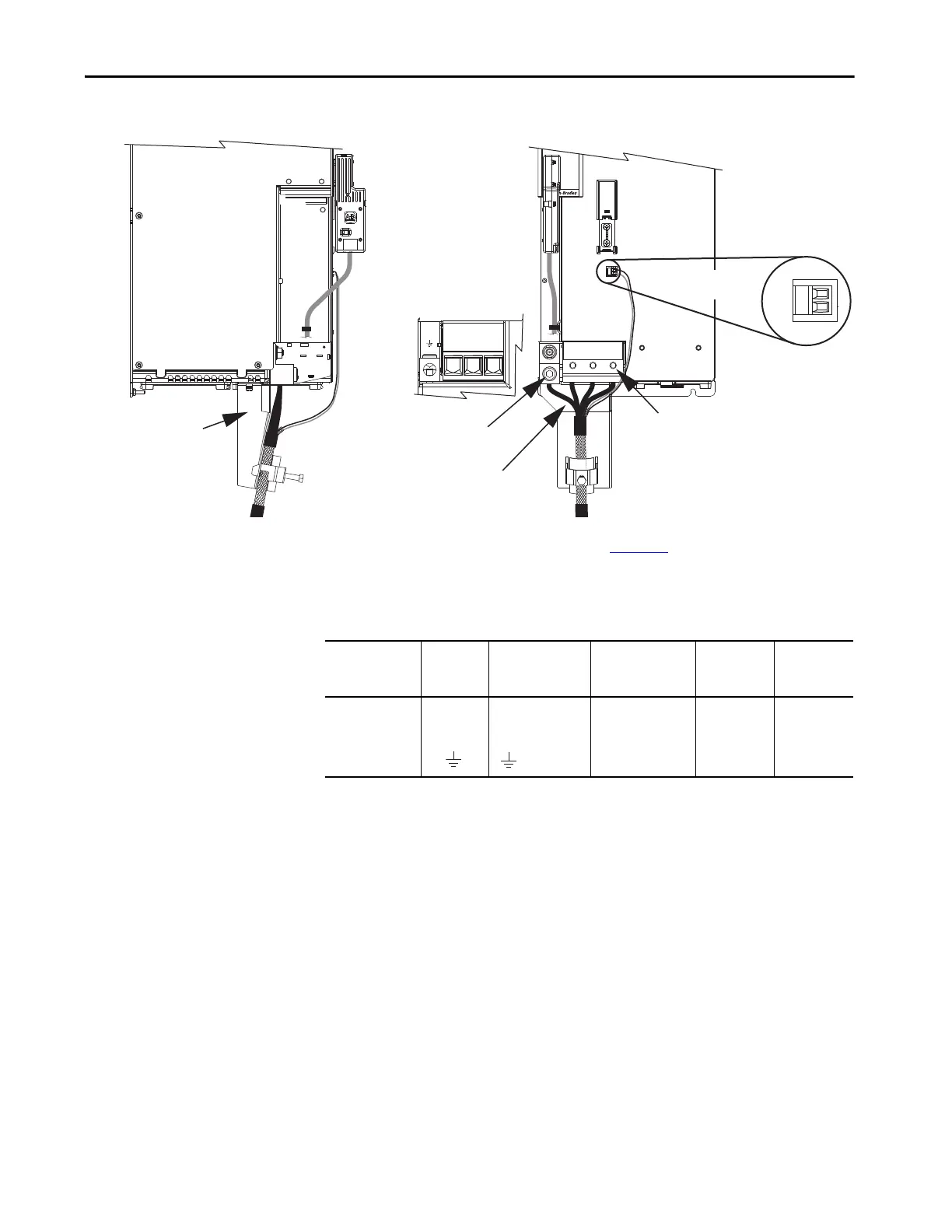
Figure 102 - MP and BC Connector Wiring (single-axis inverters)
Install the motor cable bracket (see page page 170), then attach motor power
and ground wires to the motor power connector and ground terminal. Plug in
motor feedback and brake connectors.
Table 78 - Motor Power and Brake Connector Specifications (single-axis inverters)
Maximum Cable Lengths
There are maximum cable length limitations that apply to the DC-bus cables
(cluster to cluster) and motor power/brake and feedback cables (drive to
motor).
DC Bus Cluster-to-Cluster Cable Lengths
In this example, the power supply (center) feeds two extended clusters. The
following DC-bus cable length limitations apply:
• The maximum DC-bus cable length (power supply cluster to extended
cluster) is 70 m (230 ft)
• The maximum total DC-bus cable length is 140 m (459 ft)
MBRK
+
-
21mm (4 AWG-250 kcmil)
15-20 Nm (132-177 lbin)
2
W V U
W V U
2
1
–
MBRK
+
Motor Cable
Connections
Motor Brake
(BC) Connector Plug
Motor Cable
Bracket
2198-S263-ERSx or
2198-S312-ERSx
Single-axis Inverters
(front view)
Motor Power
(MP) Connector
(bottom view)
Motor Power (MP) Connector
Screws (3x): 6 mm Hex Driver
Torque: 15…20 N•m (132…177 lb•in)
Motor Power Ground Terminal
Screw: 8 mm Hex Driver
Torque: 5.6 N•m (50 lb•in)
2198-S263-ERSx or
2198-S312-ERSx
Single-axis Inverters
(side view)
Bulletin 2090 Motor Power Cable
(2090-CPBM7DF cable is shown)
2198-K57CK-D15M
Motor Feedback
Connector Kit
Drive Module
Cat. No.
Pin Signal/Wire Color
Recommended
Wire Size
mm
2
(AWG)
Strip Length
mm (in.)
Terminal
Torque Value
N•m (lb•in)
2198-S263-ERSx
2198-S312-ERSx
21.1…120
(4…250 kcmil)
27.0 (1.06)
15…20
(132…177)
Brown
Black
Blue
Green/Yellow
U
V
W

 Loading...


