Rockwell Automation Publication 2198-UM002G-EN-P - February 2019 111
Connector Data and Feature Descriptions Chapter 4
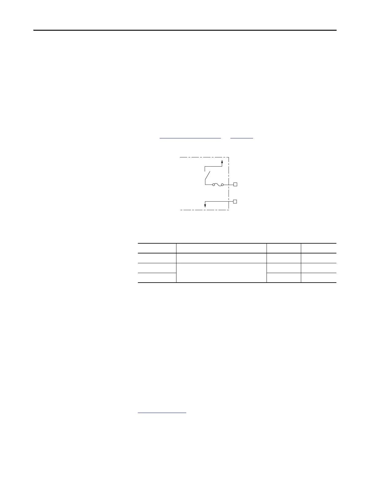
Converter OK Relay
The converter OK circuitry includes a relay-driven contact within the
2198-RPxxx regenerative bus supply. The relay provides a 24V signal to non-
Kinetix 5700 inverters indicating that they can draw power from the
regenerative power supply and that the power supply is not faulted.
Refer to Power Wiring Examples
on page 343 for wiring examples.
Figure 67 - Converter OK Relay Circuit
Current limited output with auto-resettable fuse.
Table 49 - Converter OK Relay Output Specifications
Motor Brake Circuit
The brake option is a spring-set holding brake that releases when voltage is
applied to the brake coil in the motor. The customer-supplied 24V power
supply drives the brake output through a solid-state relay. The dual-axis
inverters have separate brake circuits for each axis. The solid-state brake driver
circuit provides the following:
• Brake current-overload protection
• Brake over-voltage protection
For a detailed information on vertical loads and how the servo motor holding-
brake option can be used to help keep a load from falling, see the Vertical Load
and Holding Brake Management Application Technique, publication
MOTION-AT003
.
TIP This signal is intended for use with Kinetix 6000, Kinetix 6200, Kinetix 6500
Kinetix 7000, or PowerFlex drives when migrating from the 8720MC-RPS to
the 2198-RPxxx regenerative bus supply.
OK+
OK–
24V PWR
24V COM
Internally
Controlled
Relay
Regenerative
Bus Supply
Resettable Fuse
Attribute Value Min Max
On-state current Current flow when the relay is closed. – 0.8 A
Off-state voltage
Voltage across the contacts when the relay is open
or closed.
–0V DC
On-state voltage – 24V DC

 Loading...


