Rockwell Automation Publication 2198-UM002G-EN-P - February 2019 281
Troubleshoot the Kinetix 5700 Drive System Chapter 7
Regenerative Bus Supply
Troubleshooting
These conditions do not always result in a fault code, but can require
troubleshooting to improve regenerative bus supply performance.
No rotation
The motor connections are loose or open. Check motor wiring and connections.
Foreign matter is lodged in the motor. Remove foreign matter.
The motor load is excessive. Verify the servo system sizing.
The bearings are worn. Return the motor for repair.
The motor brake is engaged (if supplied).
• Check brake wiring and function.
• Return the motor for repair.
The motor is not connect to the load. Check coupling.
Motor overheating
The duty cycle is excessive. Change the command profile to reduce accel/decel or increase time.
The rotor is partially demagnetized causing excessive motor current. Return the motor for repair.
Abnormal noise
Motor tuning limits are set too high. Run Tune in the Logix Designer application.
Loose parts are present in the motor.
• Remove the loose parts.
• Return motor for repair.
•Replace motor.
Through bolts or coupling is loose. Tighten bolts.
The bearings are worn. Return motor for repair.
Mechanical resonance.
Notch filter can be required (refer to Axis Properties dialog box, Compliance tab
in the Logix Designer application).
Erratic operation - Motor locks into
position, runs without control or
with reduced torque.
Motor power phases U and V, U and W, or V and W reversed. Check and correct motor power wiring.
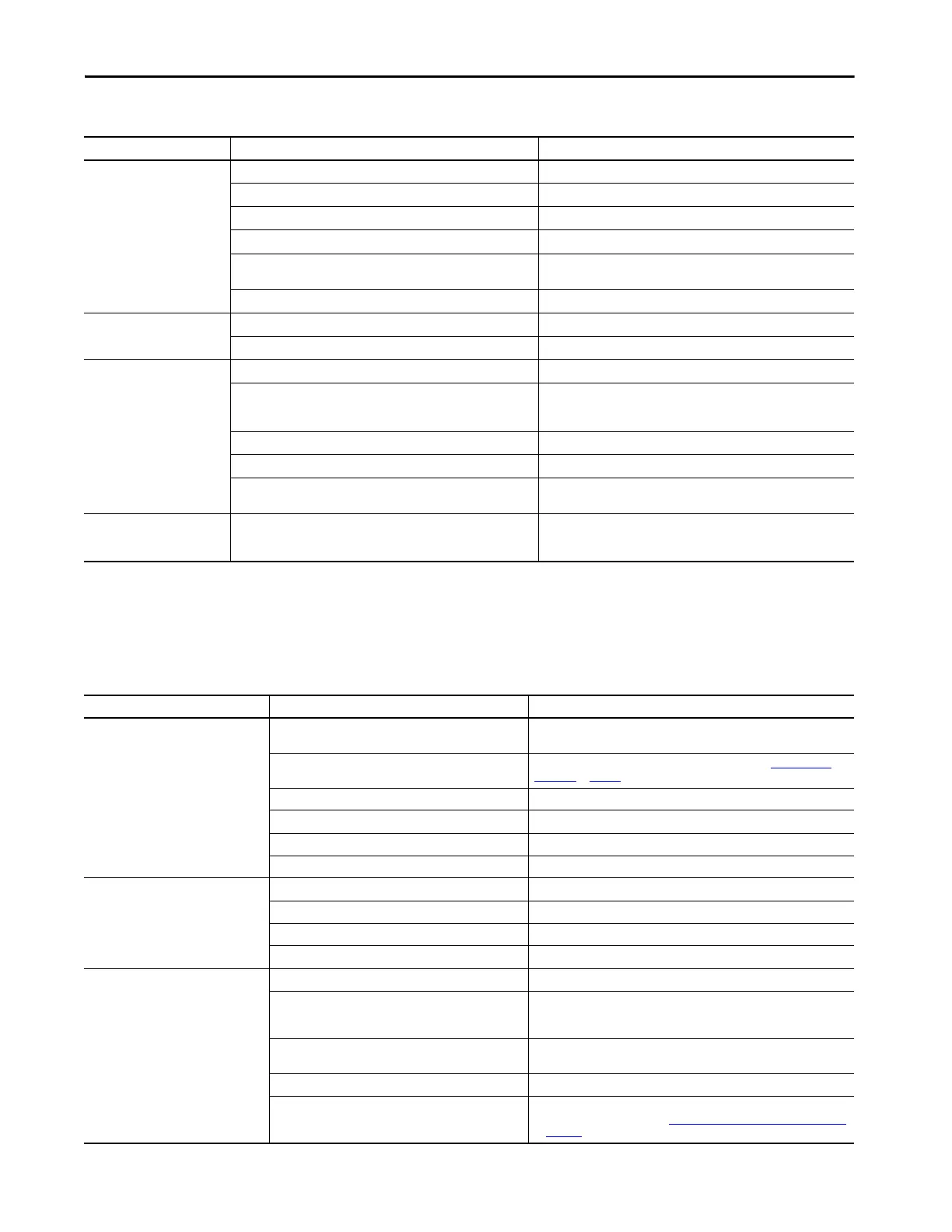
Table 129 - Axis Troubleshooting (continued)
Condition Potential Cause Possible Resolution
Table 130 - Regenerative Bus Supply Troubleshooting
Condition Potential Cause Possible Resolution
AC current appears distorted,
non-sinusoidal on oscilloscope.
AC voltage distortion.
Improve AC voltage waveform with isolation transformer or line reactor on input
power. Distortion from the utility cannot be addressed.
Excessive boost voltage.
Reduce the BusVoltageSetPoint or set to automatic mode. See DC-bus Voltage
Regulation on page 42. for definition of boost voltage.
Current Saturation. Normal operation, distortion improves closer to rated current.
Ride through condition. Normal operation, distortion clears once input voltage disturbance ends.
Load current (<50%). Normal operation, distortion improves closer to rated current.
Excessive bus stiffness. Detune the voltage and observer bandwidths.
Audible (loud) noise from regenerative bus
supply.
Excessive boost voltage. Reduce the bus voltage set point or set to automatic mode.
Notching on AC line voltage. Add isolation transformer or line reactor to isolate from notching source.
Current overload. Normal peak operation, no resolution needed.
Cooling fans enabled when AC input power is applied. Normal operation.
DC-bus voltage fluctuations.
Loop response. If changed, set loop response to medium (default).
Dynamic load change.
DC-bus voltage transient is normal with a peak-load step change, but adding a
capacitor module can help reduce voltage transients and adding an external active
shunt module can help prevent nuisance over-voltage faults.
Voltage loop or observer bandwidths.
Optimal voltage loop bandwidth setting is 1/10 of the current loop bandwidth or
lower. Optimal observer bandwidth is >2x the voltage loop bandwidth.
Normal voltage ripple of 1…2% or approximately 7…15V. Normal operation.
External bus capacitance not entered correctly.
Enter the sum of all bus capacitance external to the regenerative bus supply into
the Logix Designer application. See Calculate System and External-bus Capacitance
on page 394 to calculate external bus capacitance.

 Loading...


