Rockwell Automation Publication 2198-UM002G-EN-P - February 2019 301
Remove and Replace Drive Modules Chapter 8
Replace the Drive Module
To replace the drive module, reverse the steps that are shown above or refer to
Mount Your Kinetix 5700 Drive Modules
on page 90.
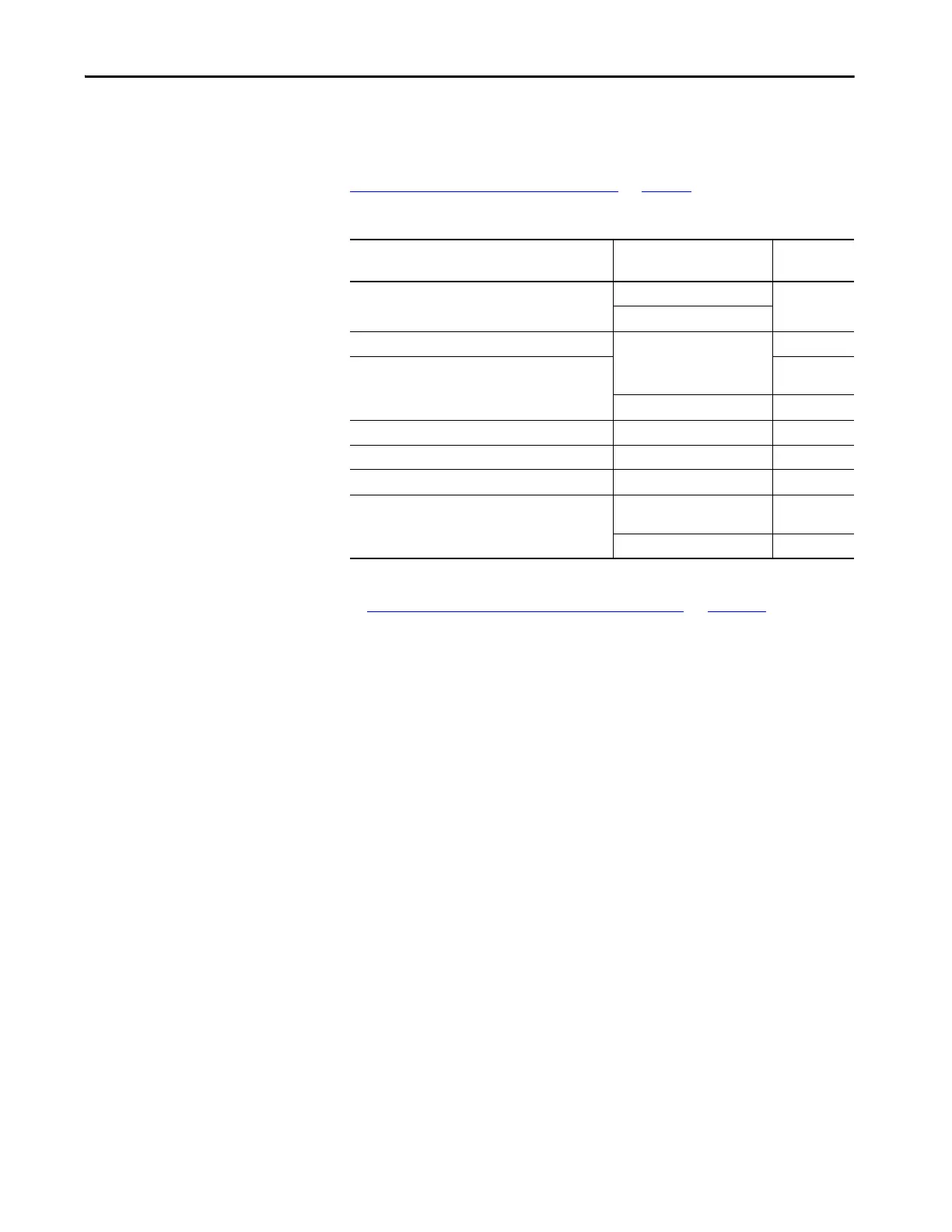
Table 147 - Drive Module Torque Values
If replacing a drive module that was configured for Integrated STO mode, refer
to Understand Integrated Safety Drive Replacement
on page 330.
Kinetix 5700 Drive Module
Cat. No.
Fasteners
Torque Value
N•m (lb•in)
All Kinetix 5700 Bulletin 2198-drive modules
Module mounting screws
4.0 (35.4)
Module ground lug
2198-Pxxx, 2198-RP088, 2198-RP200
Input power connector screws
0.8 (7.1)
2198-RP263, 2198-RP312
15…20
(132…177)
Input power ground screw 5.6 (50.0)
2198-Sxxx-ERSx Shield clamp screw 5.6 (50.0)
2198-Dxxx-ERSx, 2198-Sxxx-ERSx Feedback connector kit screws 0.4 (3.5)
2198-S086-ERSx, 2198-S130-ERSx, 2198-S160-ERSx Motor power bracket screws 0.8 (7.1)
2198-S263-ERSx, 2198-S312-ERSx
Motor power connector screws
15…20
(132…177)
Motor power ground screw 5.6 (50.0)

 Loading...


