Rockwell Automation Publication 2198-UM002G-EN-P - February 2019 87
Mount the Kinetix 5700 Drive System Chapter 3
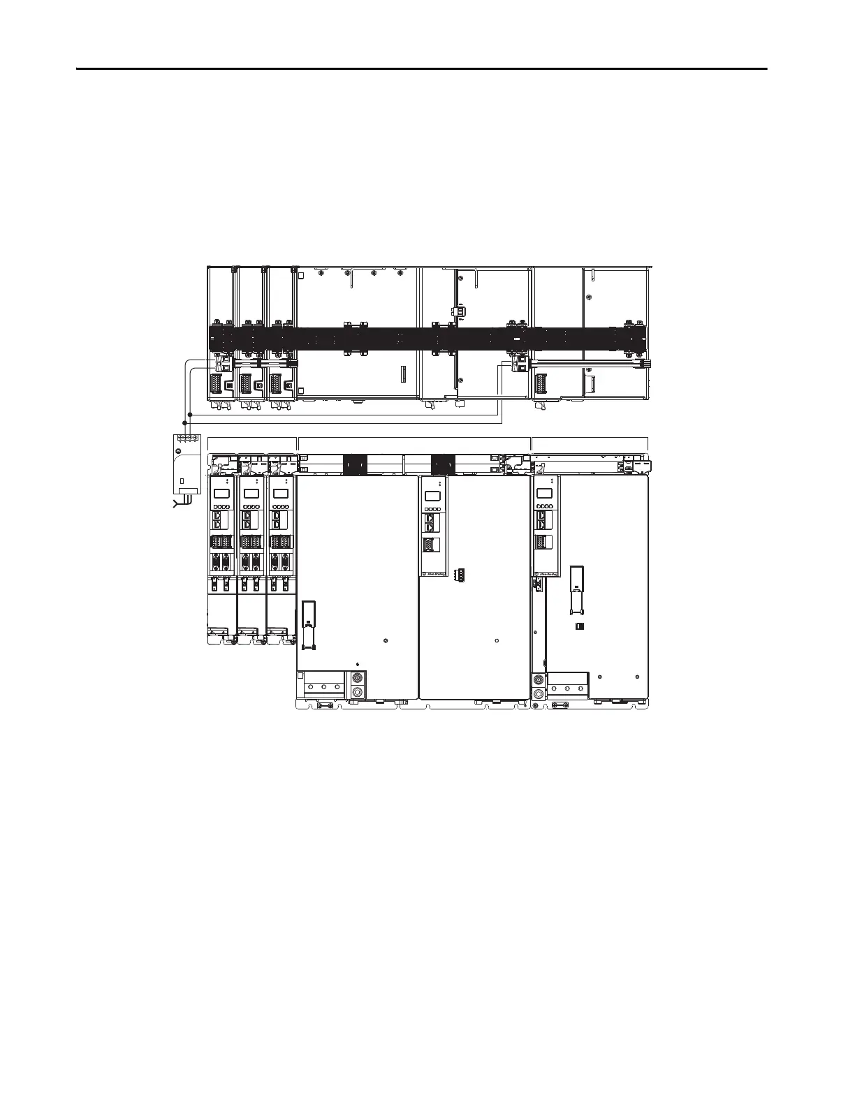
In this example, one 24V connection system spans (left to right) across the
dual-axis inverters only. In the other 24V input connection system, the
2198-S312-P-T control power T-connector and bus-bar connects the
regenerative bus supply and single-axis inverter only.
Figure 51 - Multiple 24V Input Wiring Connector Example
Drill-hole Patterns
This section provides drill-hole patterns for Kinetix 5700 drive modules that
are mounted in zero-stack (shared-bus) configurations. Properly spaced drill-
holes are essential for engaging the zero-stack tab and cutout from module-to-
module so that the DC-bus connectors are spaced properly to accept the DC-
bus links.
The DC-bus power supply and regenerative bus supply can be mounted on the
far right, far left, or anywhere in between. However, the far left position is
preferred to accommodate the 24V shared bus.
Also available to assist you in mounting Kinetix 5700 drive modules is the
2198-K5700-MOUNTKIT system mounting toolkit.
TIP 24V control power bus-bars that bridge across 2198-RPxxx regenerative bus
supplies are not available.
19
8
16
SB+/NC
NC
S1A
SCA
S2A
SB-
NC
NC
1606-XL
Power Supply
Input
Allen-Bradley
MOD
NET
2
1
1
I/O
6
5
10
MOD
NET
2
1
UFB-A UFB-B
D+
D-
MF-A MF-B
D+
D-
1
I/O-A
6
510
1
I/O-B
6
510
L1 L2 L3
19
8
16
SB+/NC
NC
S1A
SCA
S2A
SB-
NC
NC
MOD
NET
UFB-A UFB-B
D+
D-
MF-A MF-B
D+
D-
I/O-A
6
10
1
I/O-B
6
510
21mm (4 AWG-250 kcmil)
15-20 Nm (132-177 lbin)
2
19
8
16
SB+/NC
NC
S1A
SCA
S2A
SB-
NC
NC
19
8
16
SB+/NC
NC
S1A
SCA
S2A
SB-
NC
NC
MOD
NET
2
1
1
I/O
6
5
10
MBRK
+
-
21mm (4 AWG-250 kcmil)
15-20 Nm (132-177 lbin)
2
W V U
MOD
NET
UFB-A UFB-B
MF-A MF-B
D+
D-
I/O-A
6
10
1
I/O-B
6
510
1606-XLxxx
24V DC Control Power
(customer-supplied)
AC Input Power
Kinetix 5700 Servo Drive System
(front view)
Kinetix 5700 Servo Drive
System (top view)
Shared DC-bus Power
Dual-axis Inverters
Regenerative Bus Supply
Second 24V Input
Wiring Connector
Single-axis Inverter
First 24V Input
Wiring Connector

 Loading...


