148 Rockwell Automation Publication 2198-UM002G-EN-P - February 2019
Chapter 5 Connect the Kinetix 5700 Drive System
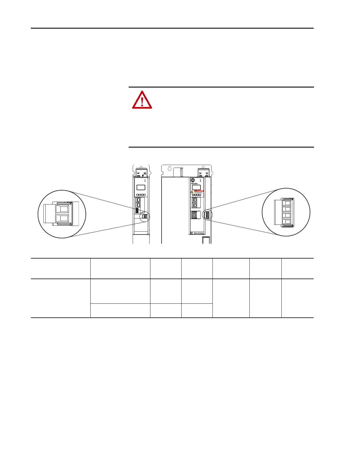
Wire the Contactor Enable Connector
The contactor enable (2-pin CED) connector applies to the DC-bus power
supply. The regenerative bus supply has a 4-pin CED connector and includes
wiring to the Converter OK relay.
Figure 96 - CED Connector Wiring - Connector Plug
Table 73 - CED Connector Plug Specifications
ATTENTION: Wiring the contactor enable relay is required. To avoid personal
injury or damage to the Kinetix 5700 drive system, wire the contactor enable
relay into your control string so that:
• three-phase power is removed and the DC-bus power supply or regenerative
bus supply is protected under various fault conditions.
• three-phase power is never applied to the Kinetix 5700 drive system before
control power is applied.
MOD–
NET–
2
1
1
4
I/O
EN–
EN+
MOD
NET
2
1
1
I/O
6
5
10
OK+
OK–
EN–
EN+
5700
OK+
OK–
EN–
EN+
2-pin Contactor Enable
(CED) Connector Plug
2198-Pxxx
DC-bus Power Supply
(front view)
2198-RPxxx
Regenerative Bus Supply
(front view)
4-pin Contactor Enable
(CED) Connector Plug
Regenerative Bus Supply
Cat. No.
DC-bus Power Supply
Cat. No.
Pin Signal
Recommended
Wire Size
mm
2
(AWG)
Strip Length
mm (in.)
Torque Value
N•m (lb•in)
2198-RP088
2198-RP200
2198-RP263
2198-RP312
2198-P031
2198-P070
2198-P141
2198-P208
EN–
EN+
CONT EN–
CONT EN+
0.14…2.5
(26…12)
7.0 (0.28)
0.4…0.5
(3.5…4.4)
–
OK+
OK–
CONV OK+
CONV OK–

 Loading...


