94 Rockwell Automation Publication 2198-UM002G-EN-P - February 2019
Chapter 4 Connector Data and Feature Descriptions
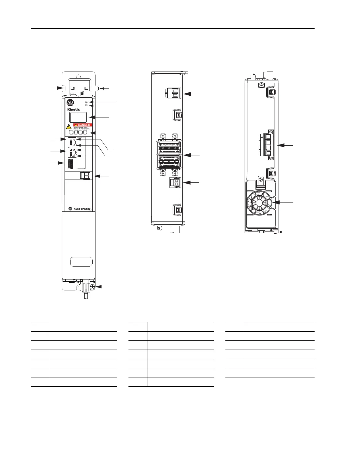
Kinetix 5700 Connector Data
Use these illustrations to identify the connectors and indicators for the
Kinetix 5700 drive modules.
Figure 55 - DC-bus Power Supply Features and Indicators
Item Description Item Description Item Description
1 Digital inputs (IOD) connector 7 LCD display 13 Shunt resistor (RC) connector
2 Ethernet (PORT1) RJ45 connector 8 Navigation pushbuttons 14 DC bus (DC) connector
3 Ethernet (PORT2) RJ45 connector 9 Link speed status indicators 15 24V control input power (CP) connector
4 Zero-stack mounting tab/cutout 10 Link/Activity status indicators 16 AC Input power (IPD) connector
5 Module status indicator 11 Contactor-enable (CED) connector 17 Cooling fan
6 Network status indicator 12 Ground terminal
5
2
10
3
7
6
9
4
4
11
15
14
8
12
1
13
MOD–
NET–
2
1
1
4
I/O
DC+
SH
DC+
DC–
24V–
24V+
L3 L2 L1
16
17
5700
DC-bus Power Supply, Top View
(2198-P031 module is shown)
DC-bus Power Supply, Bottom View
(2198-P031 module is shown)
DC-bus Power Supply, Front View
(2198-P031 module is shown)

 Loading...


