Rockwell Automation Publication 2198-UM002G-EN-P - February 2019 113
Connector Data and Feature Descriptions Chapter 4
Control Power
The Kinetix 5700 drive modules require 24V DC (21.6…26.4V) input power
for control circuitry.
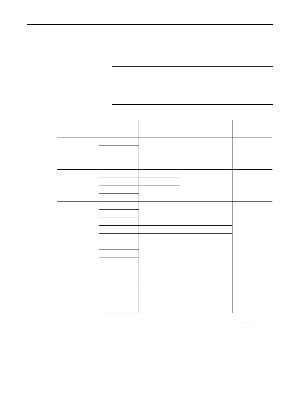
Table 50 - Control Power Current Specifications
IMPORTANT SELV or PELV rated power supplies must be used to energize external safety
devices connected to the Kinetix 5700 safety inputs.
The National Electrical Code and local electrical codes take precedence over
the values and methods provided. Implementation of these codes is the
responsibility of the machine builder.
Drive Module
Drive Module
Cat. No.
24V Current Per Module
(non-brake motor)
A
DC
24V Current, max
(with maximum brake current)
A
DC
24V Inrush Current
(5)
A
DC-bus Power Supplies
2198-P031
0.8
–4.0
2198-P070
2198-P141
1.9
2198-P208
Regenerative Bus Supplies
2198-RP088 4.3
–4.0
2198-RP200 5.4
2198-RP263
9.1
2198-RP312
Dual-axis Inverters
2198-D006-ERSx
1.4
(2)
5.5
(3)
4.0
2198-D012-ERSx
2198-D020-ERSx
2198-D032-ERSx 1.7
(2)
7.7
(3)
2198-D057-ERSx 2.3
(2)
8.3
(3)
Single-axis Inverters
2198-S086-ERSx
4.6 9.6
(4)
4.0
2198-S130-ERSx
2198-S160-ERSx
2198-S263-ERSx
2198-S312-ERSx
iTRAK Power Supply
(1)
2198T-W25K-ER 1.3 – 2.2
Capacitor Module 2198-CAPMOD-2240 0.1
–
7.0
Extension Module 2198-CAPMOD-DCBUS-IO – –
DC-bus Conditioner Module 2198-DCBUSCOND-RP312 0.1 7.0
(1) These values represent only the iTRAK power supply. They do not include the iTRAK motor modules that are connected to the iTRAK power supply and also draw current from
this 24V control power input. For more information regarding 24V control power requirements, see the iTRAK System User Manual, publication 2198T-UM001
.
(2) Values are base current per module.
(3) Values assume two brake motors, each drawing the maximum rating of 2 A, are attached to each module.
(4) Values assume the maximum rated brake current of 5 A.
(5) Inrush current duration is less than 30 ms.

 Loading...


