22 Rockwell Automation Publication 2198-UM002G-EN-P - February 2019
Chapter 1 Start
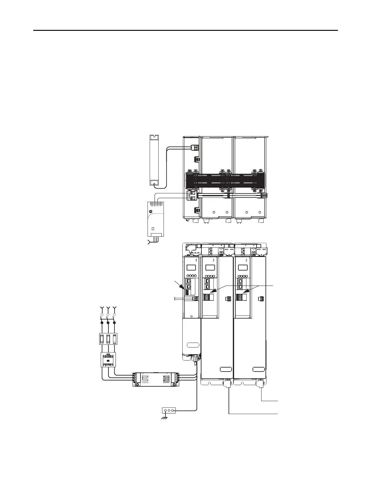
iTRAK Power Supply Configuration Example
In this example, AC input power is fed to the DC-bus (converter) power
supply. Two iTRAK power supplies support up to 40 iTRAK motor modules,
depending on cable lengths and iTRAK motor-module power consumption.
Digital inputs are wired to sensors and the control circuitry at the IOD
connectors. The contactor-enable relay protects the DC-bus power supply in
the event of shutdown fault conditions.
Figure 4 - Typical iTRAK Power Supply Installation
(1) If total control power current exceeds 16 A, a second input connector (catalog number 2198T-W25K-P-IN) can be added to the
leftmost iTRAK power supply.
2
1
16
I/O
510
–
iPS RDY
+
MOD–
NET–
1
2
3
4
5
6
7
8
9
10
MOD
NET
2
1
1
4
I/O
2
1
16
I/O
510
–
iPS RDY
+
MOD–
NET–
1
2
3
4
5
6
7
8
9
10
SH
DC+
1606-XL
Power Sup ply
Input
Allen-Bradley
Bulletin 2198
Shunt Module
(optional component)
Magnetic Contactor
(M1) Control String
1606-XLxxx
24V DC Control, Digital Inputs,
and iTRAK Motor Module Control Power
(customer-supplied)
AC Input Power
Kinetix 5700 iTRAK System
(front view)
Kinetix 5700 iTRAK System
(top view)
Line Disconnect
Device
324…528V AC
Three-phase
Input Power
Circuit
Protection
Magnetic (M1)
Contactor
Bonded Cabinet
Ground Bus
2198-DBRxx-F
AC Line Filter
(can be required for CE)
Converter Digital Inputs
iTRAK Motor Modules
DC-bus
Power Supply
iTRAK
Power Supply
iTRAK
Power Supply
iTRAK Motor Modules
iTRAK Power Supply
Digital Inputs
Shared-bus connection system for
DC-bus and 24V DC control power.
Shared DC-bus Power
Shared 24V Control Power
(1)
(24V shared-bus connection system
is optional)
2198T-CHBFLS8
Motor Power
Cables

 Loading...


