Rockwell Automation Publication 2080-UM002K-EN-E - March 2019 151
Use the High-Speed Counter and Programmable Limit Switch Chapter 8
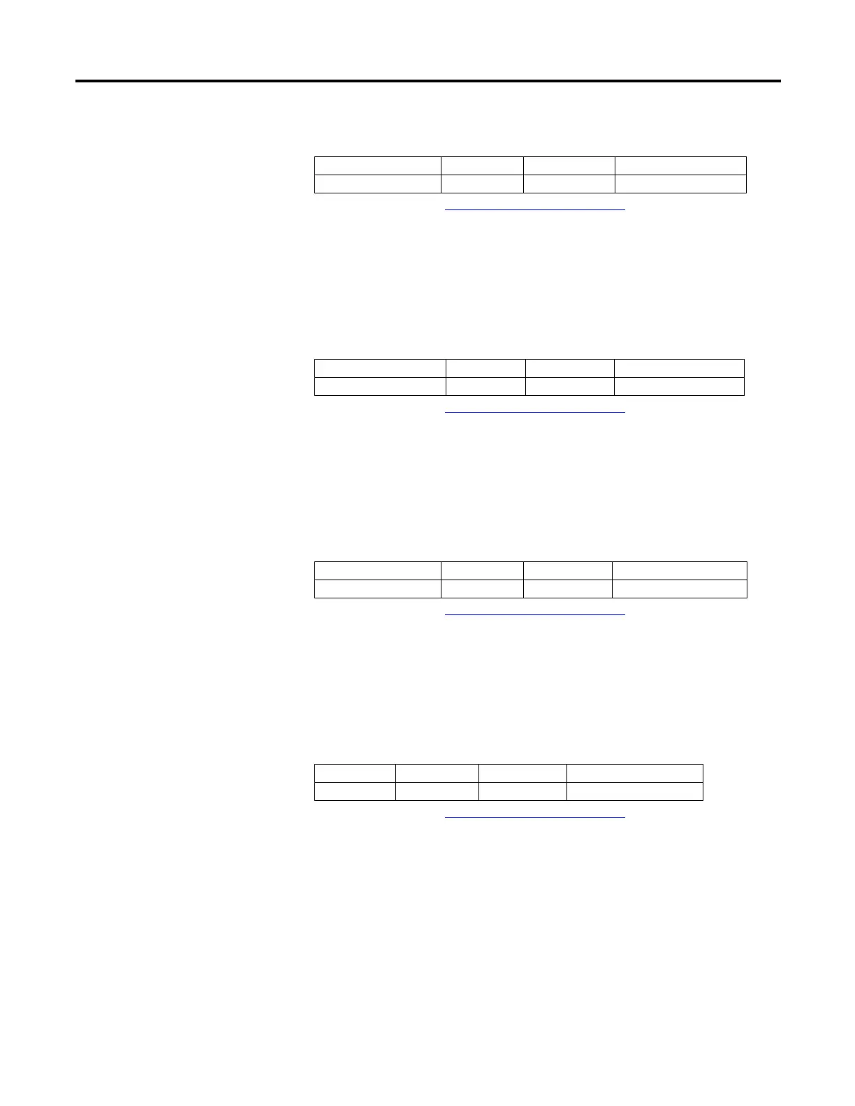
Count Up (HSCSTS.CountUpFlag)
The Count Up bit is used with all of the HSCs (modes 0…9). If the
HSCSTS.CountEnable bit is set, the Count Up bit is set (1). If the
HSCSTS.CountEnable is cleared, the Count Up bit is cleared (0).
Count Down (HSCSTS.CountDownFlag)
The Count Down bit is used with the bidirectional counters (modes 2…9). If the
HSCSTS.CountEnable bit is set, the Count Down bit is set (1). If the
HSCSTS.CountEnable bit is clear, the Count Down bit is cleared (0).
Mode Done (HSCSTS.Mode1Done)
The Mode Done status flag is set (1) by the HSC sub-system when the HSC is
configured for Mode 0 or Mode 1 behavior, and the accumulator counts up to the
High Preset.
Overflow (HSCSTS.OVF)
The HSCSTS.OVF status flag is set (1) by the HSC sub-system whenever the
accumulated value (HSCSTS.Accumulator) has counted through the overflow
variable (HSCAPP.OFSetting).
This bit is transitional and is set by the HSC sub-system. It is up to the control
program to utilize, track if necessary, and clear (0) the overflow condition.
Overflow conditions do not generate a controller fault.
Description Data Format HSC Modes
(1)
(1) For Mode descriptions, see HSC Mode (HSCAPP.HSCMode) on page 140.
User Program Access
HSCSTS.CountUpFlag bit 0…9 read only
Description Data Format HSC Modes
(1)
(1) For Mode descriptions, see HSC Mode (HSCAPP.HSCMode) on page 140.
User Program Access
SCSTS.CountDownFlag bit 2…9 read only
Description Data Format HSC Modes
(1)
(1) For Mode descriptions, see HSC Mode (HSCAPP.HSCMode) on page 140.
User Program Access
HSCSTS.Mode1Done bit 0 or 1 read/write
Description Data Format HSC Modes
(1)
(1) For Mode descriptions, see HSC Mode (HSCAPP.HSCMode) on page 140.
User Program Access
HSCSTS.OVF bit 0…9 read/write