Rockwell Automation Publication 2080-UM002K-EN-E - March 2019 45
Wire Your Controller Chapter 4
Grounding the Controller
This product is intended to be mounted to a well grounded mounting surface
such as a metal panel. Refer to the Industrial Automation Wiring and Grounding
Guidelines, publication 1770-4.1
, for additional information.
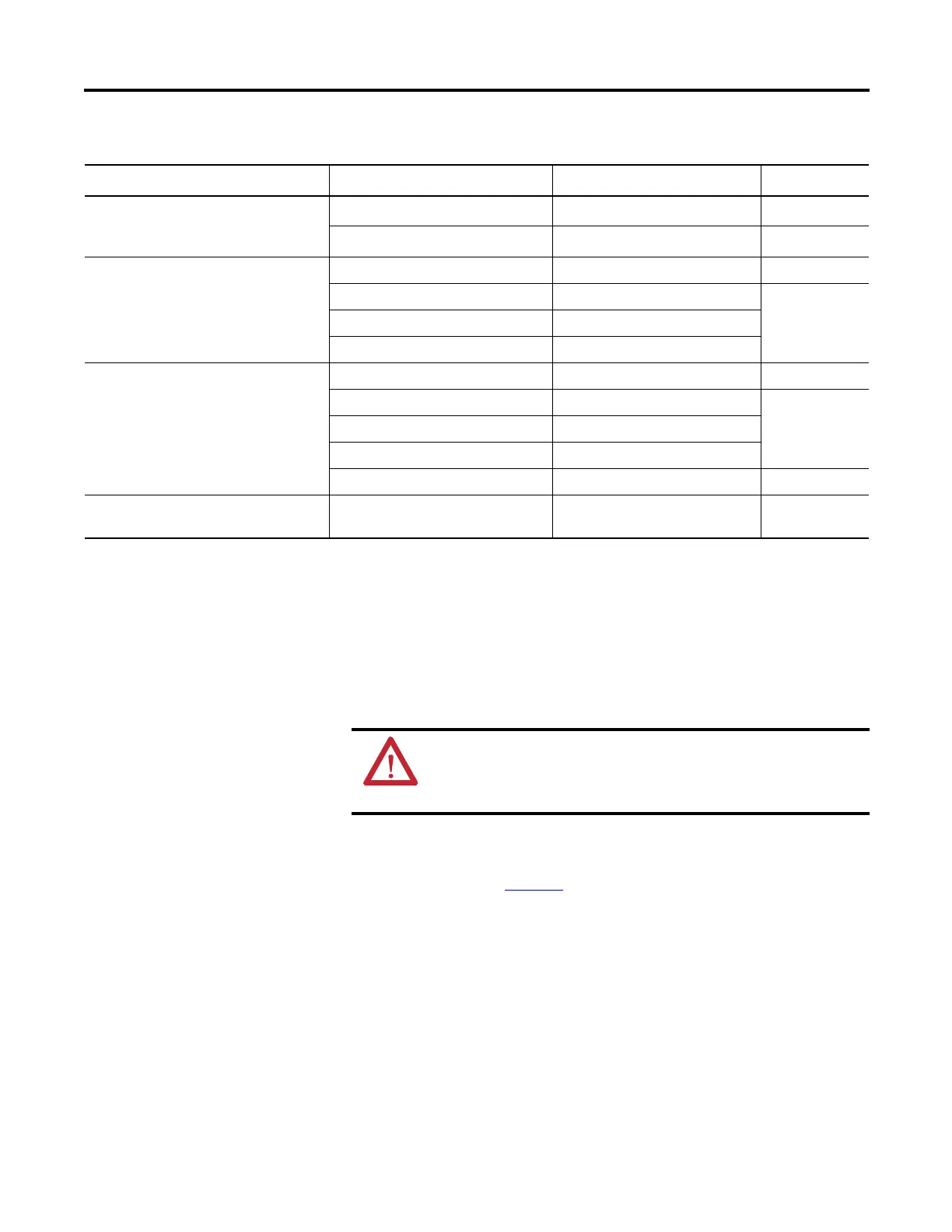
Bulletin 509 Motor Starter Size 6 12…120V AC
199-FSMA1
(2)
RC
12…120V AC
199-GSMA1
(3)
MOV
Bulletin 700 R/RM Relay AC coil Not Required
24…48V DC 199-FSMA9 MOV
50…120V DC 199-FSMA10
130…250V DC 199-FSMA11
Bulletin 700 Type N, P, PK or PH Relay 6…150V AC/DC 700-N24 RC
24…48V AC/DC 199-FSMA9 MOV
50…120V AC/DC 199-FSMA10
130…250V AC/DC 199-FSMA11
6…300V DC 199-FSMZ-1 Diode
Miscellaneous electromagnetic devices
limited to 35 sealed VA
6…150V AC/DC 700-N24 RC
(1) Catalog numbers for screwless terminals include the string ’CR’ after ’100-’. For example: Cat. No. 100-FSC48 becomes Cat. No. 100-CRFSC48; Cat. No. 100-FSV55
becomes 100-CRFSV55; and so on.
(2) For use on the interposing relay.
(3) For use on the contactor or starter.
(4) RC Type not to be used with Triac outputs. Varistor is not recommended for use on the relay outputs.
Recommended Surge Suppressors
Device Coil Voltage Suppressor Catalog Number
Type
(4)
WARNING: All devices connected to the RS-232/485 communication
port must be referenced to controller ground, or be floating (not
referenced to a potential other than ground). Failure to follow this
procedure may result in property damage or personal injury.

 Loading...


