Rockwell Automation Publication 2080-UM002K-EN-E - March 2019 83
Motion Control Chapter 7
Use the Micro800 Motion Control Feature
The Micro800 motion control feature has the following elements. New users
need to have a basic understanding of the function of each element to effectively
use the feature.
To use the Micro800 motion feature, you need to:
1. Configure the Axis Properties
See Motion Axis Configuration in Connected Components Workbench
on page 109 for instructions.
2. Write your motion program through the Connected Components
Workbench software
For instructions on how to use the Micro800 motion control feature, see
the quickstart instructions, Use the Motion Control Feature on Micro800
Controllers, publication 2080-QS001
.
3. Wire the Controller
a. refer to Input and Output Signals
on page 84 for fixed and configurable
inputs/outputs
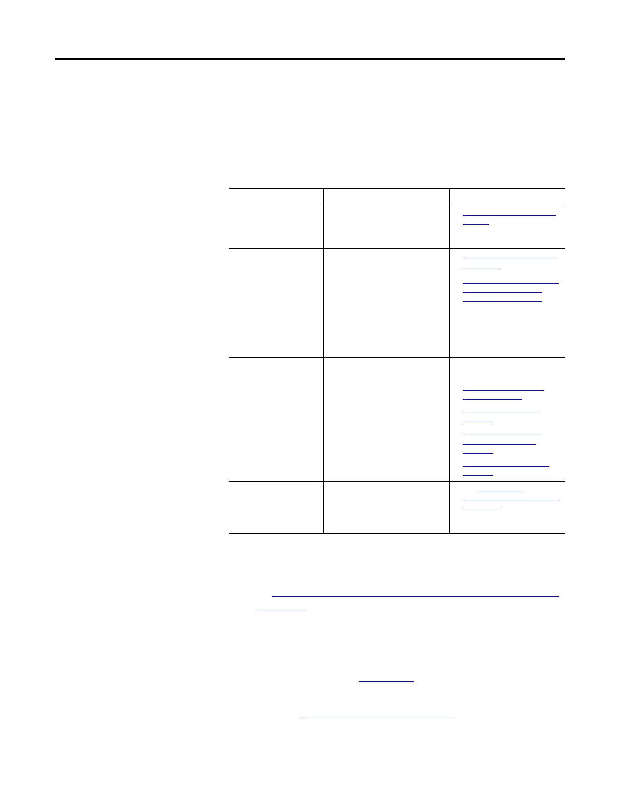
Components of Motion Control
Element Description Page
Pulse Train Outputs Consists of one pulse output and
one direction output. A standard
interface to control a servo or
stepper drive.
• Input and Output Signals
on
page 84
Axis From a system point of view, an axis
is a mechanical apparatus that is
driven by a motor and drive
combination. The drive receives
position commands through the
Micro800 pulse train outputs
interface based upon the PLC
execution of motion function blocks.
On the Micro800 controller, it is a
pulse train output and a set of
inputs, outputs, and configuration.
• Motion Axis and Parameters
on page 97
• Motion Axis Configuration in
Connected Components
Workbench on page 109
Motion Function Blocks A set of instructions that configure
or act upon an axis of motion.
• Connected Components
Workbench Online Help
• Motion Control Function
Blocks on page 87
• Axis_Ref Data Type on
page 104
• Function Block and Axis
Status Error Codes on
page 106
• Homing Function Block on
page 122
Jerk Rate of change of acceleration. The
Jerk component is mainly of
interest at the start and end of
motion. Too high of a Jerk may
induce vibrations.
• See Acceleration,
Deceleration, and Jerk Inputs
on page 89.

 Loading...


