Rockwell Automation Publication 2080-UM002K-EN-E - March 2019 135
Use the High-Speed Counter and Programmable Limit Switch Chapter 8
When using HSC function blocks, it is recommended that you:
• set HSCAppData underflow setting (UFSetting) and low preset setting
(LPSetting) to a value less than 0 to avoid possible HSC malfunction
when the HSC accumulator is reset to 0.
• set HSCAppData overflow setting (OFSetting) and high preset setting
(HPSetting) to a value greater than 0 to avoid possible HSC malfunction
when the HSC accumulator is reset to 0.
In some cases, a sub counter will be disabled by master counter mode. See the
section HSC Mode (HSCAPP.HSCMode) on page 140.
HSC Inputs and
Wiring Mapping
All Micro830, Micro850, and Micro870 controllers, except 2080-LCxx-xxAWB,
have 100 kHz high-speed counters. Each main high-speed counter has four
dedicated inputs and each sub high-speed counter has two dedicated inputs.
You must set a proper value for the variables OFSetting, HPSetting, and
UFSetting before triggering Start/Run HSC. Otherwise, the controller will
be faulted. (Setting a value for LPSetting is optional for certain counting
modes.)
To learn more about HscAppData variable input, see HSC APP Data
Structure on page 139.
HSC0 is used in this document to define how any HSC works.
The HSC function can only be used with the controller’s embedded I/O.
It cannot be used with expansion I/O modules.
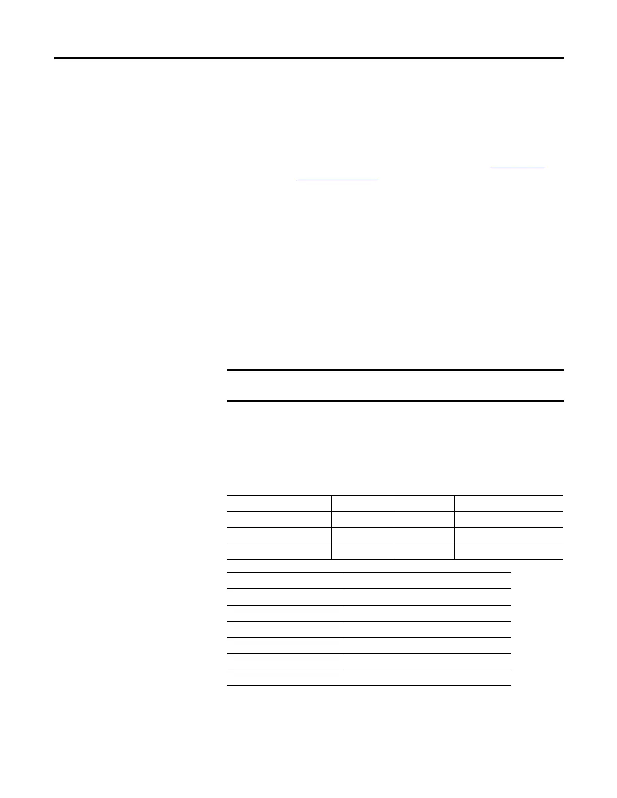
Micro830, Micro850, and Micro870 High Speed Counters
10/16-point 24-point 48-point
Number of HSC 2 4 6
Main high-speed counters 1 (counter 0) 2 (counter 0,2) 3 (counters 0, 2 and 4)
Sub high-speed counters 1 (counter 1) 2 (counter 1,3) 3 (counters 1, 3 and 5)
High Speed Counter Inputs used
HSC0 0, 1, 2, 3
HSC1 2, 3
HSC2 4, 5, 6, 7
HSC3 6, 7
HSC4 8, 9, 10, 11
HSC5 10, 11

 Loading...


