Publication 1734-UM014A-EN-P - November 2010
4 About the Adapters
• These removal and return situations exist whether the system is under
power or not. If the system is under power, the situation arises
immediately. If the system is not under power, the situation arises in the
next power cycle.
Power Up a System for the First Time
When you power the I/O for the first time, the adapter must assign slot
addresses to every module in the backplane. All I/O modules ship configured
at the same address.
When you first apply power, we expect that all but one module on the
backplane exhibits a solid red Module Status LED.
One by one the adapter resets these modules and addresses them
appropriately. The amount of time that this operation takes is proportional to
the size of your I/O system.
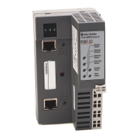
Adapter Features
Features of the adapters include:
• Use of EtherNet/IP messages encapsulated within standard
TCP/UDP/IP protocol
• Common application layer with ControlNet and DeviceNet networks
• Interfacing via Category 5 rated twisted pair cable
• Half/full duplex 10 Mbit or 100 Mbit operation
• DIN rail mounting for 1734-AENTR adapter/Wall or panel mounting
for 1738-AENTR adapter
• Communication to and from other I/O modules on the same DIN rail
for 1734-AENTR adapter/Communication to and from other I/O
modules in the chassis for 1738-AENTR adapter
• Communication supported by RSLinx software
• IP address assigned via standard BootP or DHCP tools
• I/O configuration via RSLogix 5000 software
• No network scheduling required
• No routing tables required
• Support of connections from multiple controllers simultaneously
Hardware/Software
Compatibility
The I/O adapters and the applications described in this manual are compatible
with the following firmware revisions and
software releases.
 Loading...

