EasyManuals Logo
Home>Allen-Bradley>Recording Equipment>PowerFlex 20-HIM-A6

Allen-Bradley PowerFlex 20-HIM-A6 User Manual

Allen-Bradley PowerFlex 20-HIM-A6
74 pages
To Next Page IconTo Next Page
To Previous Page IconTo Previous Page
Page #15 background imageLoading...
Page #15 background image
Rockwell Automation Publication 20HIM-UM001D-EN-P - February 2013 15
Installing the HIM Chapter 2
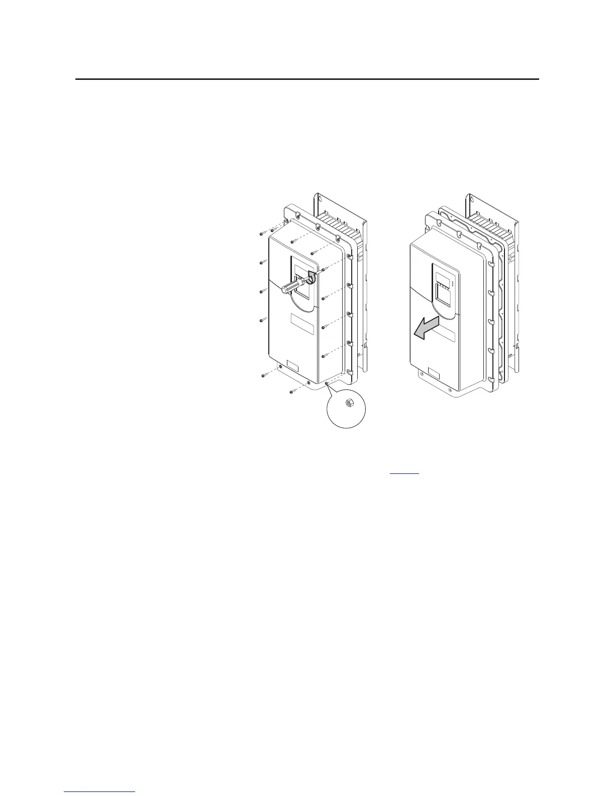
PowerFlex 750-Series IP54, NEMA/UL Type 12 Drives
1. Unfasten and remove the cover as shown below using the following
recommended tools:
Screwdriver: 6.4 mm (0.25 in.) flat or T20 Hexalobular
Hex socket: 7 mm
2. Place the HIM into the drive HIM bezel by inserting it straight back into
the top of the bezel and then sliding it down into the base of the bezel onto
the mating connector as shown on page 14
.
3. Replace the cover and the fasteners.
4. Tighten all screws and nuts to the recommended torque of 0.68 N•m (6.0
lb•in).
2x:
M4 x 0.7

Table of Contents

Questions and Answers:

Question and Answer IconNeed help?

Do you have a question about the Allen-Bradley PowerFlex 20-HIM-A6 and is the answer not in the manual?

Allen-Bradley PowerFlex 20-HIM-A6 Specifications

General IconGeneral
BrandAllen-Bradley
ModelPowerFlex 20-HIM-A6
CategoryRecording Equipment
LanguageEnglish

Related product manuals