14 Rockwell Automation Publication 20HIM-UM001D-EN-P - February 2013
Chapter 2 Installing the HIM
Installing the 20-HIM-A6 HIM
The 20-HIM-A6 (NEMA Type 1) HIM is normally installed in the HIM bezel
(drive Port 1) on the front of the drive. For temporary hand-held operation, the
HIM can be plugged into drive Port 2 (near the bottom of the drive control pod
for PowerFlex 750-Series drives, or on the bottom of the drive for PowerFlex 7-
Class drives) using a 1 m/3.28 ft. long 20-HIM-H10 cable. For applications
requiring the HIM to be located remotely, the HIM can be installed in a remote-
mount HIM bezel (catalog number 20-HIM-B1) in a suitable location. The 20-
HIM-B1 remote-mount HIM bezel includes a 3 m/9.8 ft. long 1202-C30 cable.
In the Drive HIM Bezel
PowerFlex 750-Series IP20, NEMA/UL Open Type Drives
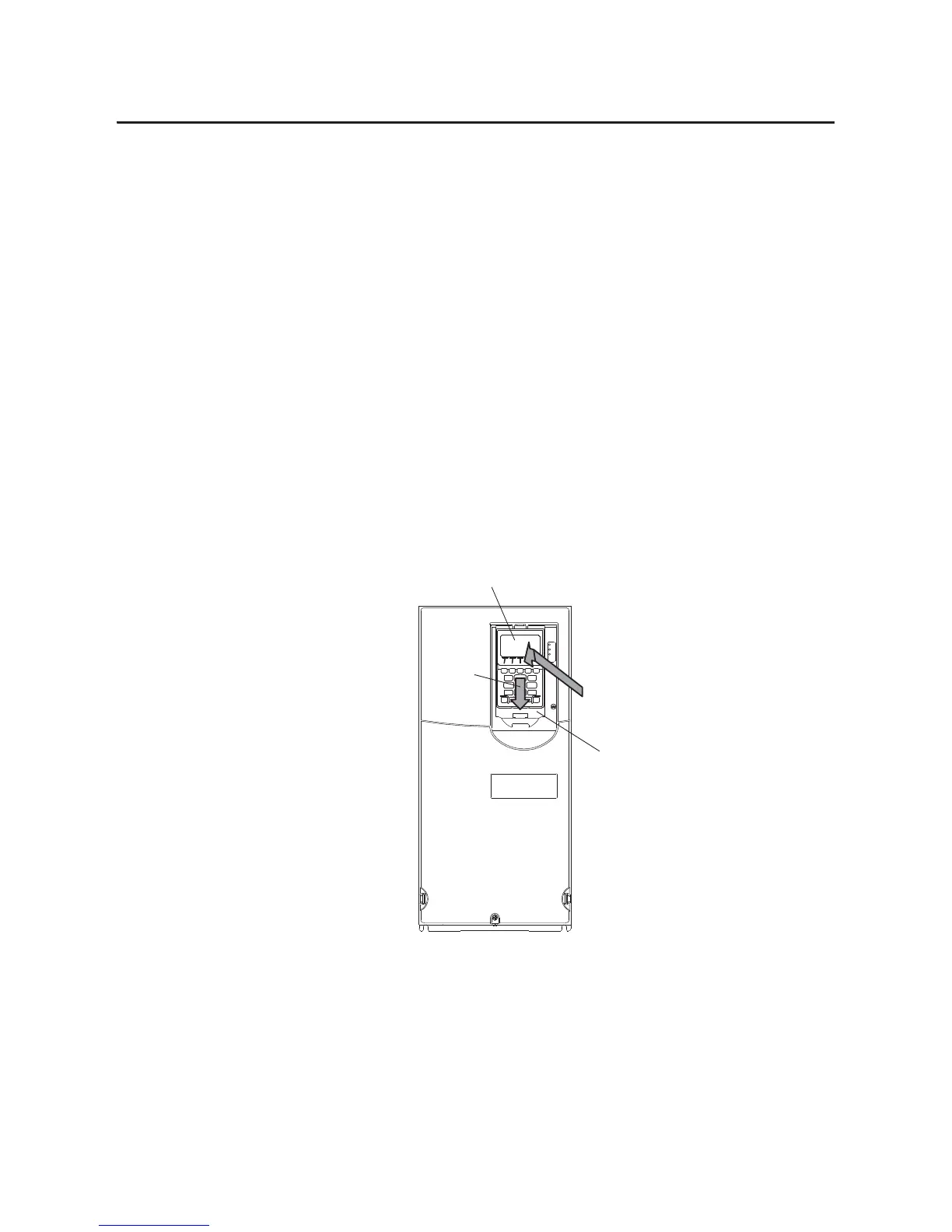
Place the HIM into the drive HIM bezel by inserting it straight back into the top
of the bezel and then sliding it down into the base of the bezel onto the mating
connector.
The HIM can be installed in the drive HIM bezel with the drive powered or
unpowered.
(PowerFlex 755 drive shown)
Drive HIM Bezel
20-HIM-A6 HIM
➊ IN
➋ DOWN
 Loading...