Rockwell Automation Publication 20HIM-UM001D-EN-P - February 2013 17
Installing the HIM Chapter 2
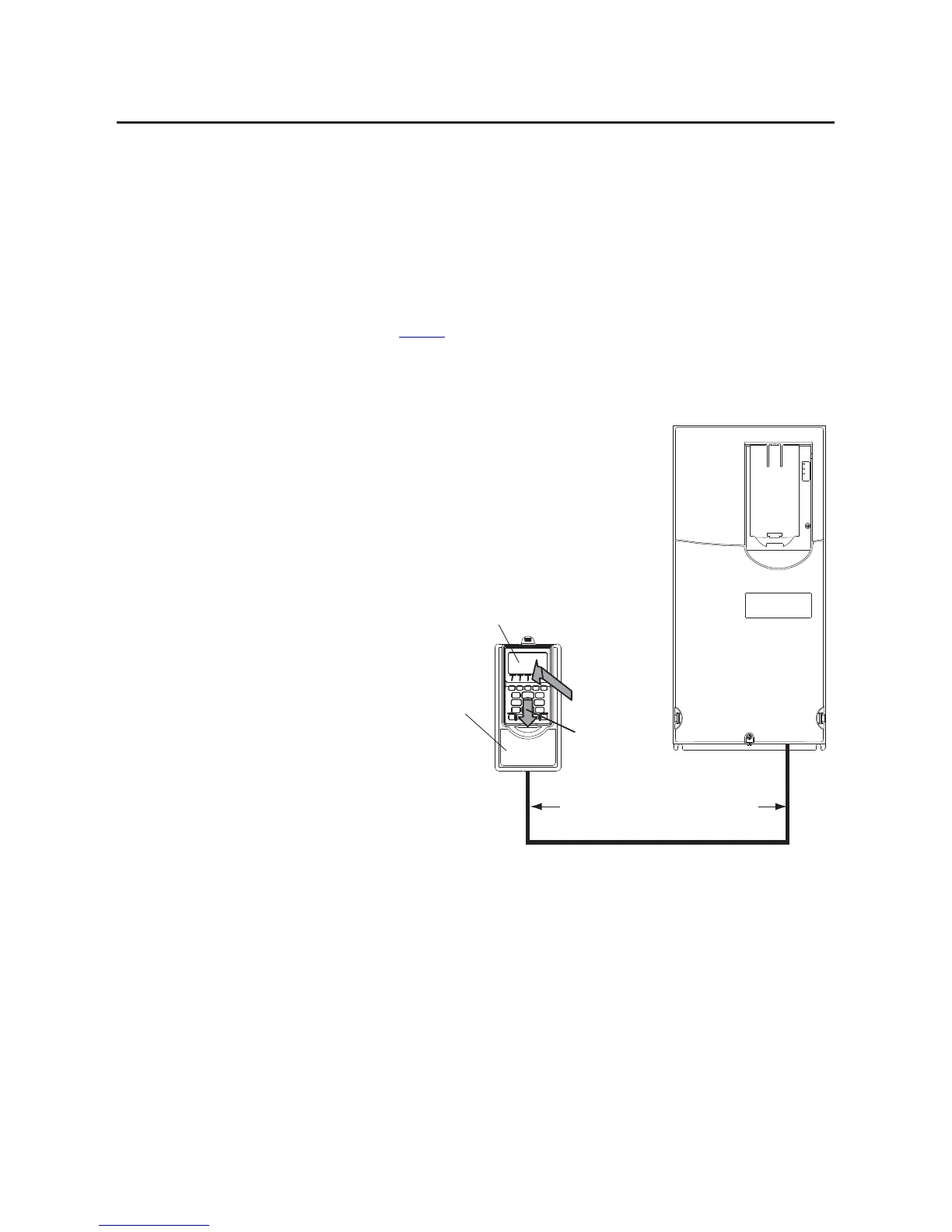
In a Remote-Mount HIM Bezel (20-HIM-B1)
1. If the remote-mount HIM bezel is not mounted, see the HIM Bezel
Installation Instructions, publication 20HIM-IN002, for mounting
details.
2. Route the 3 m/9.8 ft. long 1202-C30 bezel cable (included with the 20-
HIM-B1 remote-mount HIM bezel) to the drive.
3. Connect the bezel cable to the DPI Port 2 on the drive as shown on
page 16
for a PowerFlex 750-Series drive or a PowerFlex 7-Class drive.
4. Install the HIM into the remote-mount HIM bezel.
PowerFlex 755 drive shown
(without HIM in drive HIM bezel)
20-HIM-B1
Remote-Mount
HIM Bezel
3 m/9.8 ft. long 1202-C30 bezel cable included
with 20-HIM-B1 remote-mount HIM bezel.
Distances can be increased up to 75 m/246 ft.
(1)
(1) To increase this distance, use one of the following cables:
• 1202-H03 Extension cable (0.3 m/0.98 ft. long)
• 1202-H13 Extension cable (1.0 m/3.28 ft. long)
• 1202-H30 Extension cable (3.0 m/9.8 ft. long)
• 1202-CBL-KIT-100M cable
Note that a cable distance greater than 30 m/98.4 ft. is not CE compliant.
20-HIM-A6 HIM
➍ b. Slide down.
➍ a. Push in.
 Loading...