212 Rockwell Automation Publication 750-PM001N-EN-P - February 2017
Chapter 4 Port 10 and Port 11 Parameters
Inverter (Port 10) Common
Parameters
Inverter Common parameters apply only to PowerFlex 755 Frame 8 and larger
drives.
File
Group
No. Display Name
Full Name
Description
Values
Read-Write
Data Type
INVERTER COMMON
System Ratings
1 Sys Rated Amps
System Rated Amps
Displays the continuous current rating of the drive. This parameter is the same value as
displayed in P21 [Rated Amps] for the drive at Port 0.
Units:
Default:
Min/Max:
Amps
0.00
0.00 / Dependent on Frame Rating
RO Real
2 Sys Rated Volts
System Rated Volts
Input voltage class (400, 480, 600, 690, etc) of the drive. This parameter is the same
value as displayed in P20 [Rated Volts] for the drive at Port 0.
Units:
Default:
Min/Max:
V AC
0.00
0.00 / 690.00
RO Real
3
4
5
I1 Rated Amps
I2 Rated Amps
I3 Rated Amps
Inverter n Rated Amps
Continuous current rating of inverter n. The continuous current rating varies based on
the value of P305 [Voltage Class] and P306 [Duty Rating] for the drive at Port 0.
Units:
Default:
Min/Max:
Amps
0.00
0.00 / 1000.00
RO Real
21 Effctv I Rating
Effective Inverter Rating
Sets the effective inverter current rating. During N-1 operation, the effective inverter
current rating is reduced from P21 [Rated Amps].
Units:
Default:
Min/Max:
Amps
0.0
0.0 / Dependent on Frame Rating
RO Real
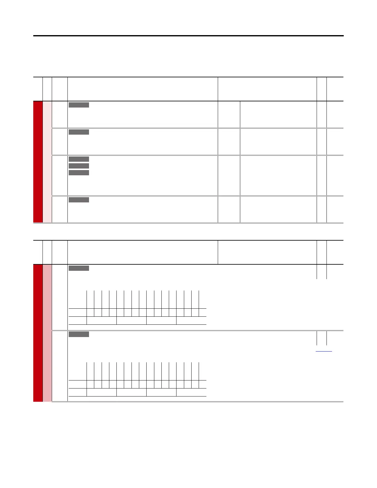
File
Group
No. Display Name
Full Name
Description
Values
Read-Write
Data Type
INVERTER COMMON
Status
10 Online Status
Online Status
RO 16-bit
Integer
Indicates whether the inverter has successfully established fiber optic communications with the main control board.
12 Fault Status
Fault Status
RO 16-bit
Integer
Indicates whether the inverter has a fault condition. See P105 [I1 Fault Status] to view which fault conditions currently exist for inverter 1. Refer to Chapter
6 for
information on fault and alarm codes.
Options
Reserved
Reserved
Reserved
Reserved
Reserved
Reserved
Reserved
Reserved
Reserved
Reserved
Reserved
Reserved
Reserved
Reserved
Inverter 2
Inverter 1
Default0000000000000000
Bit 1514131211109876543210
0 = Not Active
1 = Active
Options
Reserved
Reserved
Reserved
Reserved
Reserved
Reserved
Reserved
Reserved
Reserved
Reserved
Reserved
Reserved
Reserved
Reserved
Inverter 2
Inverter 1
Default0000000000000000
Bit 1514131211109876543210
0 = Not Faulted
1 = Faulted

 Loading...


