306 Rockwell Automation Publication 750-PM001N-EN-P - February 2017
Chapter 6 Troubleshooting
Power Layer Interface (PLI)
Board 7-Segment Display
PowerFlex 755 Frame 8 and larger drives provide a pair of 7-segment displays to
indicate drive status and conditions.
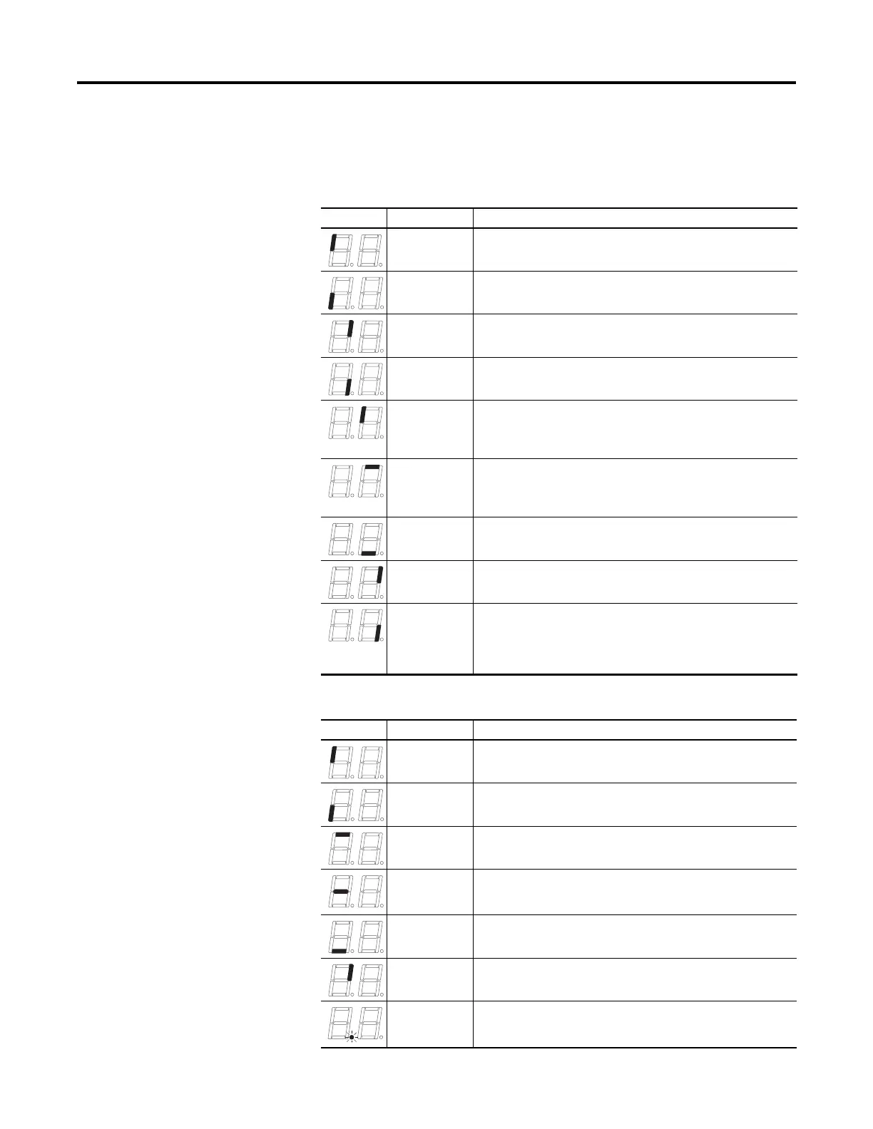
Series A Display
Series B Display
Lit Segment Indication Description
Fault Clear Indicates that a fault condition has been cleared.
Fault Indicates that a fault condition exists.
Power On Indicates that power is applied to the PLI board.
Charged Indicates the state of the pre-charge pin.
PWM Enable IGBT gating is enabled. When disabled, all IGBT signal inputs to the PLI IGBT
driver chip are low. IGBT gating is enabled by setting bit 0 of the Config Register.
IGBT gating is disabled by clearing bit 0 or by “POE” fault (IOC, Bus Overvoltage,
or Ground Fault).
Fiber Loss Fault Turns on when a Fiber Loss fault occurs. A Fiber Loss fault occurs when the LOS
signal is high or when a valid data packet has not been received for 1024 μs. The
fault is latched and is cleared by setting bit 8 of the Config Register. The Fiber
Loss fault inhibits IGBT firing in the same manner as a “POE” fault.
Fiber Loss Pin Indicates that the actual state of the LOS pin described in Write Enable.
SAFE Vcc Power On Power is applied to the PLI IGBT driver chip (U14). Delayed for 12 seconds after
power-up.
Write Enable Data writes from the fiber-optic link are enabled to PLI registers. Data writes are
disabled for ten seconds (time that is required for the Control Board to initialize)
after negation of the LOS pin of the PLI fiber-optic transceiver. LOS is driven high
when the optical power into the fiber-optic receiver is too low (broken, crimped,
disconnected fiber, or transmitter at opposite end of fiber is not operating.
Lit Segment Indication Description
PWM Enable IGBT gating is enabled. IGBT gating is enabled by setting bit 0 of the Config
Register. IGBT gating is disabled by clearing bit 0 or by fault.
Fault Indicates that a fault condition exists.
Initialization Done Indicates that the control has initialized the PLI board.
Fiber Loss Actual state of the LOS pin. LOS is driven high when the optical power into the
fiber-optic receiver is too low (broken, crimped, disconnected fiber, or
transmitter at opposite end of fiber is not operating.
On Line The PLI is powered.
System Safety
Enable B
Pin 1 of the 541 PLI IGBT driver chip (U14) is low. This pin must be low to fire the
IGBTs.
Aux Power A 24V auxiliary supply provide power for the PLI board.

 Loading...


