486 Rockwell Automation Publication 750-PM001N-EN-P - February 2017
Appendix D Using DeviceLogix
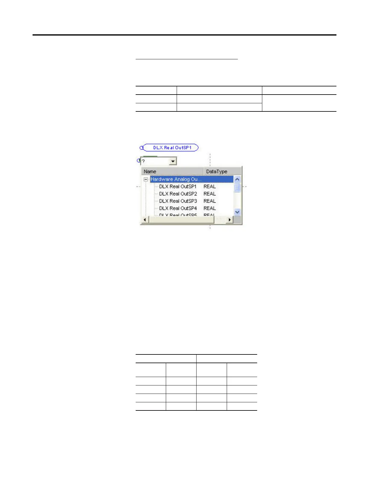
Example 2 – Writing data to the network
The DeviceLogix program controls an Analog Output value, which is written to
DLX Real OutSP1.
DLX Real OutSP1 can now be used as a Hardware Analog Output and used
directly with a Function Block (a DeviceLogix Datalink is not required).
Program Examples
Example 1: Selector Switch Operation
This example demonstrates how a selector switch operation similar to the feature
in the PowerFlex 700S can be achieved through the embedded DeviceLogix in
the PowerFlex 750-Series drive. A selector switch is simulated in the drive by
using a combination of inputs to produce multiple outputs. Digital inputs in the
drive are used to output configurable multiple preset speeds (75 Hz, 85 Hz, 95
Hz, and 105 Hz) to P571 [Preset Speed 1]. It is assumed that the 750-Series drive
has an I/O module that is installed in Port 4.
The following truth table represents the inputs and outputs for a 4 position
selector switch.
The Logic Map offers a high-level explanation of how these outputs are achieved.
Drive Datalink Value
753 Port 0 P905 [Data Out A1] Port 14: DLX Real OutSP1
755 Port 13 P17 [DL To Net 01]
Inputs Outputs
Input 1Input 2Binary OutputSelector Switch
Output
000Output A
011Output B
102Output C
113Output D

 Loading...


