48 Rockwell Automation Publication 750-PM001N-EN-P - February 2017
Chapter 3 Drive Port 0 Parameters
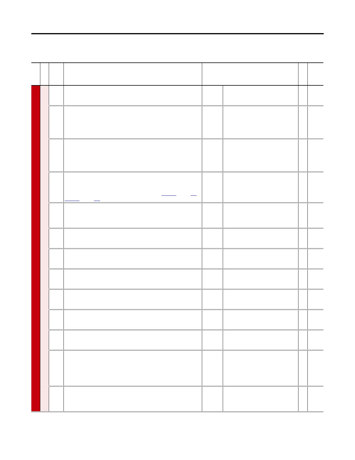
Drive (Port 0) Monitor File
File
Group
No. Display Name
Full Name
Description
Values
Read-Write
Data Type
MONITOR
Metering
1 Output Frequency
Output Frequency
Output frequency present at terminals T1, T2, and T3 (U, V & W)
Units:
Default:
Min/Max:
Hz
0.00
–/+650.00
RO Real
2 Commanded SpdRef
Commanded Speed Reference
Value of the active Speed/Frequency Reference. Displayed in Hz or RPM, depending on
the value of P300 [Speed Units].
Units:
Default:
Min/Max:
Hz
RPM
0.00
–/+P27 [Motor NP Hertz] x 8
–/+P28 [Motor NP RPM] x 8
RO Real
3 Mtr Vel Fdbk
Motor Velocity Feedback
Estimated or actual motor speed, with feedback. Displayed in Hz or RPM, depending
on the value of P300 [Speed Units].
Units:
Default:
Min/Max:
Hz
RPM
0.00
–/+P27 [Motor NP Hertz] x 8
–/+P28 [Motor NP RPM] x 8
RO Real
4 Commanded Trq
Commanded Torque
External torque regulation reference. Summation of Torque A Select Reference and
Torque B Select Reference. Percent of motor rated torque. See Figure 21
on page 377 or
Figure 61 on page 420.
Units:
Default:
Min/Max:
%
0.00
–/+800.00
RO Real
5 Torque Cur Fdbk
Torque Current Feedback
Based on the motor, the amount of current that is in phase with the fundamental
voltage component.
Units:
Default:
Min/Max:
Amps
Based on Drive Rating
–/+P21 [Rated Amps] x 2
RO Real
6 Flux Cur Fdbk
Flux Current Feedback
Amount of current that is out of phase with the fundamental voltage component.
Units:
Default:
Min/Max:
Amps
Based on Drive Rating
–/+P21 [Rated Amps] x 2
RO Real
7 Output Current
Output Current
The total output current present at terminals T1, T2, and T3 (U, V & W).
Units:
Default:
Min/Max:
Amps
Based on Drive Rating
0.00 / P21 [Rated Amps] x 2
RO Real
8Output Voltage
Output Voltage
Output voltage present at terminals T1, T2, and T3 (U, V & W).
Units:
Default:
Min/Max:
V AC
Based on Drive Rating
0.00 / P20 [Rated Volts] x 1.15
RO Real
9Output Power
Output Power
Output power present at terminals T1, T2, and T3 (U, V & W).
Units:
Default:
Min/Max:
kW
0.00
0.00 / 3000.00
RO Real
10 Output Powr Fctr
Output Power Factor
Output power factor.
Default:
Min/Max:
0.00
0.00 / 1.00
RO Real
11 DC Bus Volts
Direct Current Bus Volts
DC bus voltage.
Units:
Default:
Min/Max:
V DC
Based on Drive Rating
0.00 / P20 [Rated Volts] x 2
RO Real
12 DC Bus Memory
Direct Current Bus Memory
A six-minute average of P11 [DC Bus Volts] used to estimate the DC equivalent of the
input voltage. Automatically initialized upon power-up or precharge, continually
updated during normal operation, and is used to trigger a power loss condition. Use
P464 [DC Bus Mem Reset] to reset this parameter.
Units:
Default:
Min/Max:
V DC
Based on Drive Rating
0.00 / P20 [Rated Volts] x 2
RO Real
13 Elapsed MWH
Elapsed Megawatt Hour
Accumulated output energy of the drive. Use P336 [Reset Meters] to reset this
parameter.
Units:
Default:
Min/Max:
MWh
0.000
0.000 / 4294967296.000
RO Real

 Loading...


