Rockwell Automation Publication 750-PM001N-EN-P - February 2017 271
Embedded Feature and Option Module Parameters Chapter 5
Universal Feedback Module
Parameters
File
Group
No. Display Name
Full Name
Description
Values
Read-Write
Data Type
Universal Feedback
Module
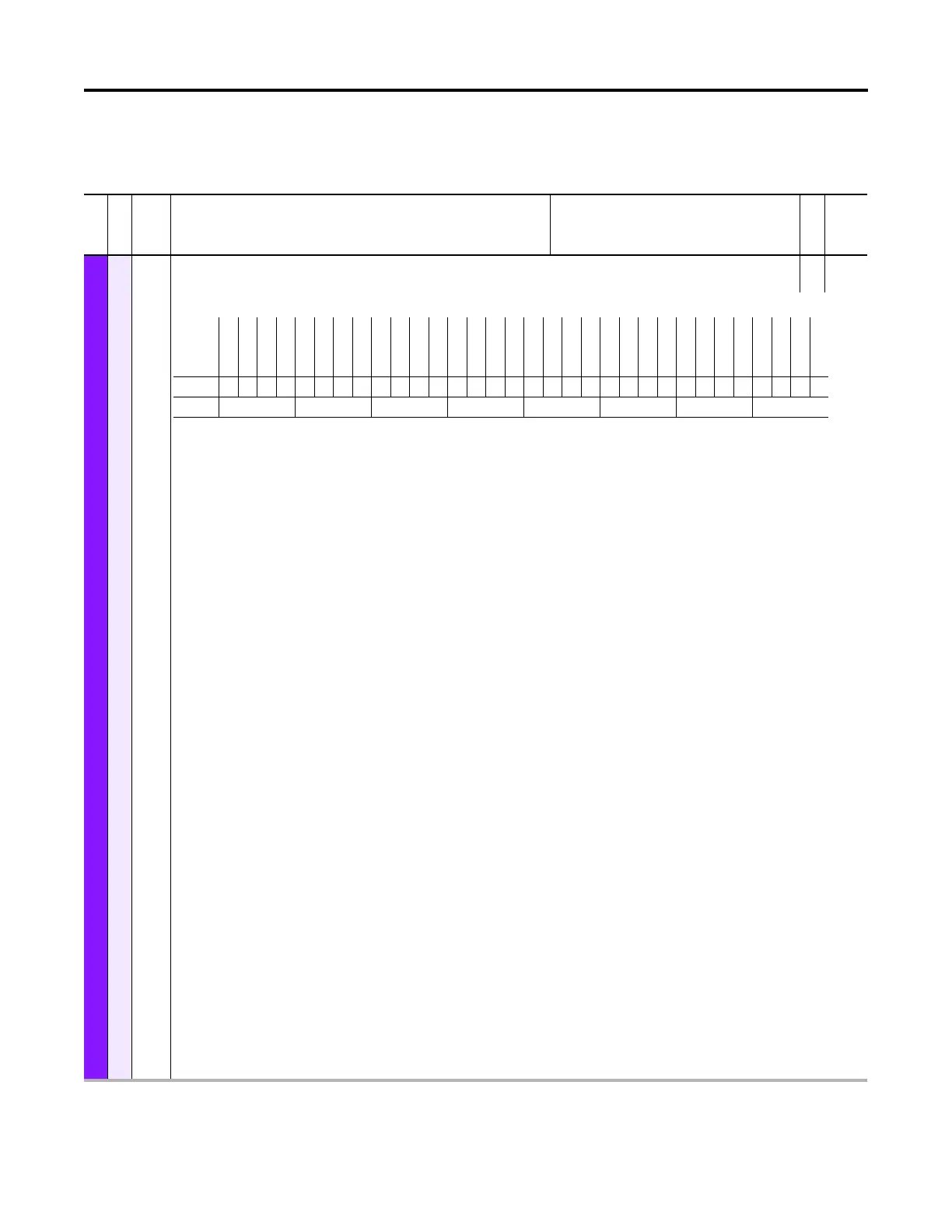
1Module Sts
Module Status
RO 16-bit
Integer
Shows error and alarm information of the Feedback Option module.
Bit 0 “Module Error” – Indicates that the Feedback Option module has any error. This bit is set if at least one of the bits “FB0 Error”, “FB1 Error”, or “System Error” is
set.
Bit 1 “Alarm Type 1” – Indicates that there is any alarm of type 1 active on the Feedback Option module. Bits 8…10 indicate what kind of alarm is active.
Bit 2 “Alarm Type 2” – Indicates that there is any alarm of type 2 active on the Feedback Option module. Bits 20 and 21 indicate what kind of alarm is active.
Bit 4 “FB0 Error” – Indicates that Feedback 0 has an error. This bit is set if any Feedback 0 error bit in P10 [FB0 Sts] is set. If this bit is set, Bit 0 “Module Error” is also
set.
Bit 5 “FB1 Error” – Indicates that Feedback 1 has an error. This bit is set if any Feedback 1 error bit in P10 [FB1 Sts] is set. If this bit is set, Bit 0 “Module Error” is also
set.
Bit 6 “System Error” – Indicates that there is a feedback independent error on the Feedback Option module. Bits 12 and 13 show the type of the System Error. If this
bit is set, Bit 0 “Module Error” is also set.
Bit 8 “FB0 Alarm” – Indicates that feedback device 0 has an alarm. This bit is set if there is an alarm in the Feedback 0 encoder. If this bit is set, Bit 1 “Alarm Type 1”
and P10 [FB0 Sts] Bit 12 “Encoder Alm” will also be set. The specific alarm condition may be shown in a status found under the diagnostics tab for the Universal
Feedback Module. Separate diagnostic items are provided for both ports and for both of the following devices: EnDat and BiSS. Alarm conditions for Linear Stahl
feedback devices can be found in P27 [FB0 LinStahl Sts] and P57 [FB1 LinStahl Sts].
Bit 9 “FB1 Alarm” – Indicates that feedback device 1 has an alarm. This bit is set if there is an alarm in the Feedback 1 encoder. If this bit is set, Bit 1 “Alarm Type 1”
and P40 [FB1 Sts] Bit 12 “Encoder Alm” will also be set. The specific alarm condition may be shown in a status found under the diagnostics tab for the Universal
Feedback Module. Separate diagnostic items are provided for both ports and for both of the following devices: EnDat and BiSS. Alarm conditions for Linear Stahl
feedback devices can be found in P27 [FB0 LinStahl Sts] and P57 [FB1 LinStahl Sts].
Bit 10 “Cfg Alarm” – Indicates that there is a feedback independent alarm on the Feedback Option module. Bits 16 and 17 show the type of the Cfg Alarm. If this bit
is set, Bit 1 “Alarm Type 1” is also set.
Bit 12 “Hardware Err” – Indicates that there is a Hardware Error on the Feedback Option module. If this bit is set, Bit 6 “System Error” is also set. The hardware is self
tested by the board at powerup. Specific details of the hardware failure are not available.
Bit 13 “Firmware Err” – Indicates that there is a Firmware Error on the Feedback Option module. A Firmware Error occurs if the Hardware and the downloaded
Firmware are not compatible. If this bit is set, Bit 6 “System Error” is also set.
Bit 16 “EncOut Cflct” – If set, there is one of the following problems with the Encoder Output:
• The selection in P80 [Enc Out Sel] is not possible since the required pins on the terminal blocks are already used for Feedback 0 or 1 according to P6 [FB0 Device
Sel] and P36 [FB1 Device Sel].
• P80 [Enc Out Sel] is set to “Sine Cosine” and there is no signal connected to the pins 1-4 of the Terminal Block 1.
• P80 [Enc Out Sel] is set to “Sine Cosine”, the value of [FBn IncAndSC PPR] is not a power of two, and the parameter P84 [Enc Out Z PPR] is not set to 0 “1 ZPulse.”
This is not allowed.
• P80 [Enc Out Sel] is set to “Channel X” or “Channel Y” and there is no encoder connected to that channel.
• P80 [Enc Out Sel] is set to “Channel X” or “Channel Y” and there is a linear encoder connected to this channel. If this bit is set, Bit 10 “Cfg Alarm” is also set.
Bit 17 “Safety Cflct” – If set, the Safety DIP switches are in an invalid position. If this bit is set, Bit 10 “Cfg Alarm” is also set.
Bit 20 “FB0FB1 Cflct” – If set, the combination of the feedback selection done with the parameters P6 [FB0 Device Sel] and P36 [FB1 Device Sel] is invalid, i.e. both
feedbacks have Sin-Cos-Signals (There is only place for one set of Sin-Cos-Signals on the Terminal Blocks). If this bit is set, Bit 2 “Alarm Type 2” is also set.
Bit 21 “Initializing” – Indicates that the Universal Feedback State Machine is in the Initialize State. This Type 2 alarm makes sure that the motor cannot be started
during the initialization state. If this bit is set, Bit 2 “Alarm Type 2” is also set.
Bit 29 “Pri Safety” – Indicates that the UFB is used as primary safety module.
Bit 30 “Sec Safety” – Indicates that the UFB is used as secondary safety module.
Bit 31 “DPI Ready” – This bit tells the MCB if the UFB is ready for DPI communication.
Options
DPI Ready
Sec Safety
Pri Safety
Reserved
Reserved
Reserved
Reserved
Reserved
Reserved
Reserved
Initializing
FB0FB1 Cflct
Reserved
Reserved
Safety Cflct
EncOut Cflct
Reserved
Reserved
Firmware Err
Hardware Err
Reserved
Cfg Alarm
FB1 Alarm
FB0 Alarm
Reserved
System Error
FB1 Error
FB0 Error
Reserved
Alarm Type 2
Alarm Type 1
Module Error
Default00000000000000000000000000000000
Bit 313029282726252423222120191817161514131211109876543210
0 = False
1 = True

 Loading...


