Publication 1747-RM001G-EN-P - November 2008
Block Transfer Instructions 8-3
• Control - The control block is an integer data file address that stores all
the block transfer control and status information. The control block is
three words in length. Note that these integer file addresses should not
be used for any other instructions. You should provide the following
information for the control structure.
–Rack - The I/O rack number (0 to 3) of the I/O chassis in which
you placed the target I/O module.
–Group - The I/O group number (0 to 7) which specifies the position
of the target I/O module in the I/O chassis. When using 1/2-slot
addressing, only even group numbers are valid.
–Slot - The slot number (0 or 1) within the group. When using 2-slot
addressing, the 0 slot is the low (right) slot and the 1 slot is the high
(left) slot within the group. When using 1-slot or 1/2-slot addressing,
always select slot 0.
– Requested Word Count - The number of words to transfer. If you
set the length to 0, the processor reserves 64 words for block transfer
data. The block transfer module transfers the maximum words the
adapter can handle. If you set the length from 1 to 64, the processor
transfers the number of words specified.
Control Status Bits
To use the BTR and BTW instructions correctly, examine the instruction’s
control and status bits stored in the control structure. These bits are mapped
to bits in word 0 of the control block structure.
TIP
The three-word control block has the following
structure. Before executing a block transfer, the BTR
and BTW instructions clear all status bits and
initialize word 2 to 0. See Table 8.2, “Control Block
Structure,” for more information.
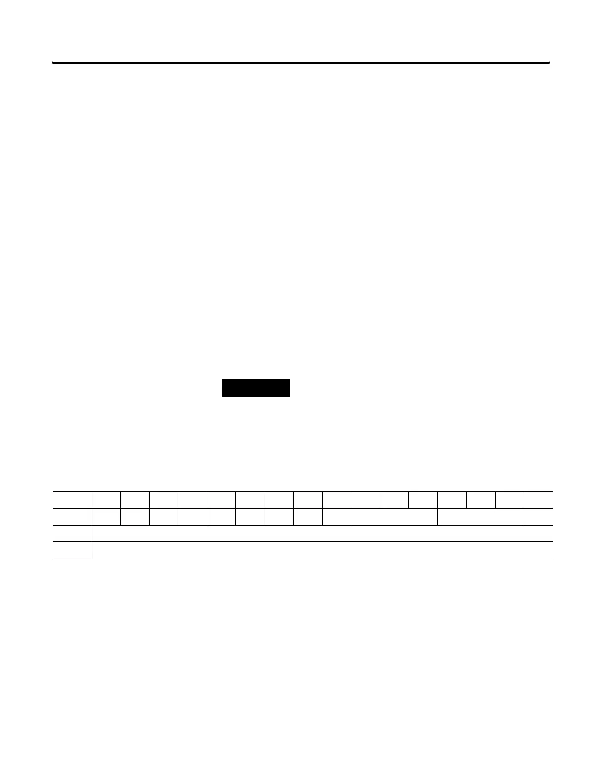
Table 8.2 Control Block Structure
15 14 13 12 11 10 9 8 7 6 5 4 3 2 1 0
Word 0 EN ST DN ER EW TO RW Rack Group Slot
Word 1 Requested word count
Word 2 Transmitted word count/Error code

 Loading...


