Publication 1747-RM001G-EN-P - November 2008
SLC Communication Instructions 12-13
MSG Instruction Setup Screen Parameters
Parameters for This Controller
• Data Table Address
– For a Read, this is the starting address which receives the data that is
read from the target device.
– For a Write, this is the starting address of the data which is written to
the target device.
– For Modbus RTU Master, this is the starting address to receive or
send data.
• Size in Elements
– Specifies the length of the message in elements. The maximum
number of elements that are transferred via a MSG instruction is
determined by the size of the destination data type.
– For a Read, the data type in the local processor determines the
maximum number of elements.
– For a Write, the data type in the target device determines the
maximum number of elements. The maximum number of elements
that are transferred may be further limited based on the processor
type.
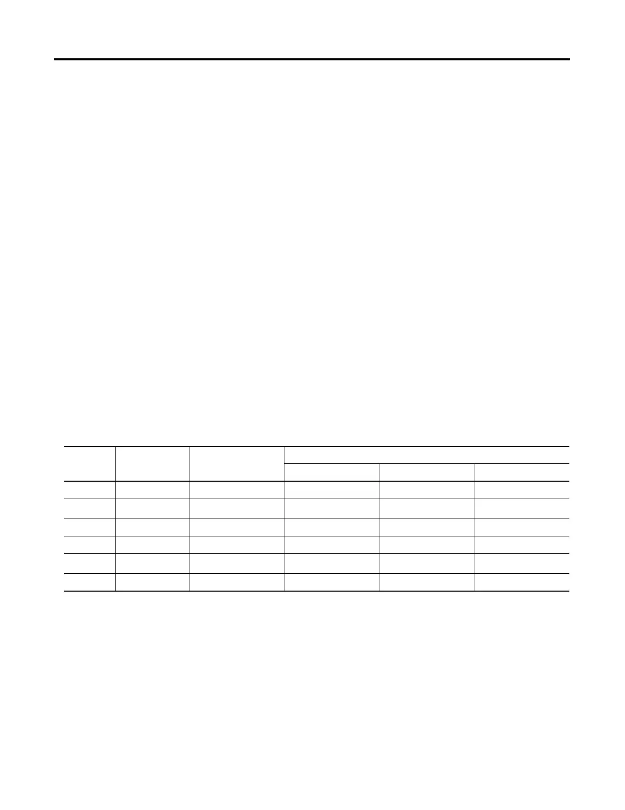
Table 12.5 MSG Instruction Maximum Number of Elements (except Modbus RTU)
File Types SLC 500, SLC
5/01, SLC 5/02
SLC 5/03, SLC 5/04,
SLC 5/05 Channel 0
SLC 5/05 Channel 1
Non-Multihop Multihop to SLC Multihop to PLC-5
O, I, B, N 41 103 256 119 115
T13
34
(1)
256
(3)
39
38
(4)
C, R 13 34 256 39 38
F Not Applicable 51 256 59 57
St Not Applicable
2
(2)
25 2 1
A Not Applicable 103 256 119 115
(1)
PLC-5 type timer element maximum is 20.
(2)
PLC-5 type string element maximum is 1.
(3)
PLC-5 type timer element maximum is 208.
(4)
PLC-5 type timer element maximum is 23.

 Loading...


