Publication 1747-RM001G-EN-P - November 2008
Basic Instructions 2-13
Counter Instructions
Overview
How Counters Work
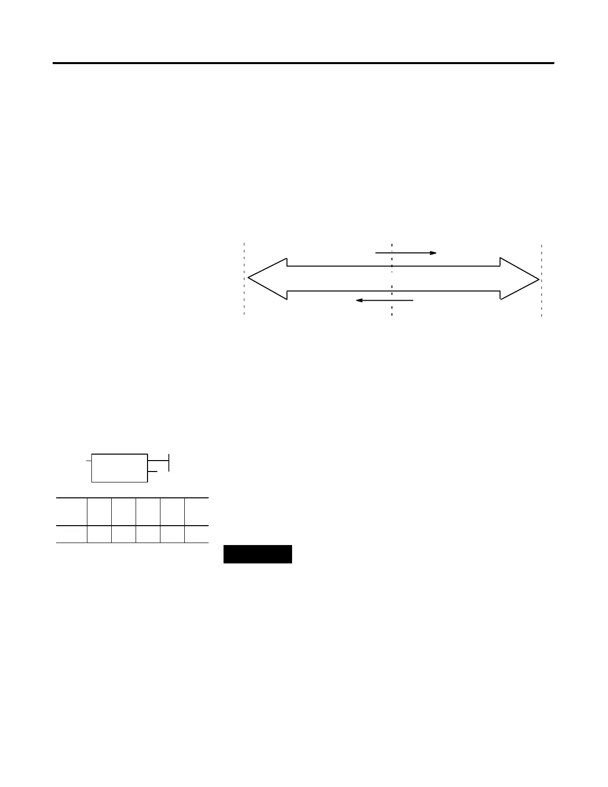
The figure below demonstrates how a counter works. The count value must
remain in the range of − 32768 to + 32767. If the count value goes above +
32767 or below − 32768, the counter status overflow (OV) or underflow (UN)
bit is set.
A counter can be reset to zero using the reset (RES) instruction.
Count Up (CTU)
The CTU is an instruction that counts false-to-true rung transitions. Rung
transitions can be caused by events occurring in the program (from internal
logic or by external field devices) such as parts traveling past a detector or
actuating a limit switch.
When rung conditions for a CTU instruction have made a false-to-true
transition, the accumulated value is incremented by one count, provided that
the rung containing the CTU instruction is evaluated between these
transitions. The ability of the counter to detect false-to-true transitions
depends on the speed (frequency) of the incoming signal.
The accumulated value is retained when the rung conditions again become
false. The accumulated count is retained until cleared by a reset (RES)
instruction that has the same address as the counter reset.
-32,768
Underflow
(CTU)
Count Up
0
Count Down
(CTD)
+32,767
Overflow
Counter Accumulated Value
(CU)
(DN)
CTU
COUNT UP
Counter C5:0
Preset 120
Accum 0
Output Instruction
Fixed SLC
5/01
SLC
5/02
SLC
5/03
SLC
5/04
SLC
5/05
• •••••
TIP
The on and off duration of an incoming signal must
not be faster than the scan time x2 (assuming a 50%
duty cycle).

 Loading...


