Publication 1747-RM001G-EN-P - November 2008
4-20 Math Instructions
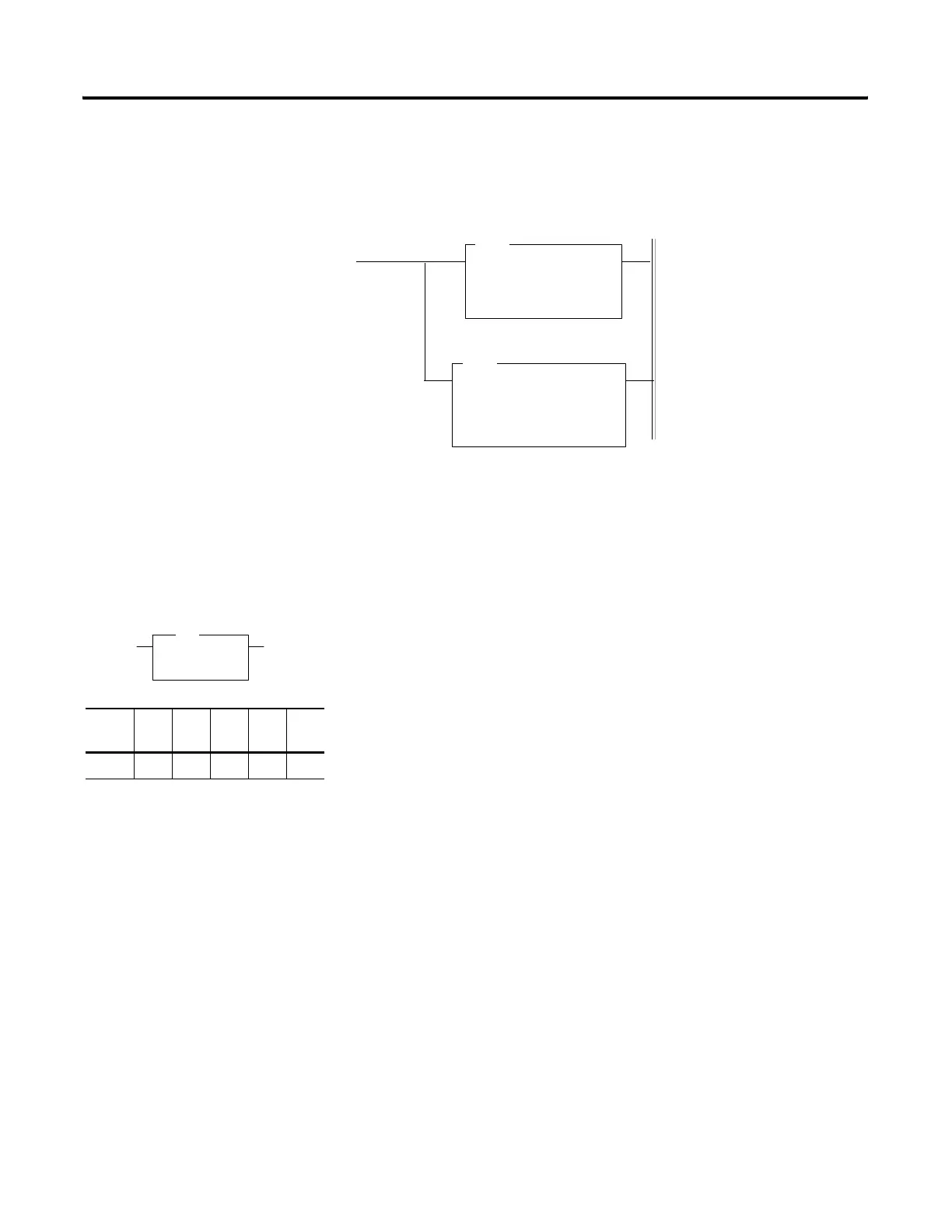
In this example, the SCL instruction is entered in the ladder logic program as
follows.
Ramp Instruction (RMP)
The Ramp (RMP) instruction provides the ability to create linear, acceleration,
deceleration, and “S” curve ramp output data wave forms. This instruction
provides a means to ramp analog outputs when using them to control devices
such as valves.
The instruction has the following parameters.
• Control - Control Block is an integer file address that is user selectable.
It is a 7-element file, which consists of the following bits and registers:
– Word 0 Bit 15 - Enable bit, follows rung state of ramp instruction.
– Word 0 Bit 14 - Ramping bit, when set, RMP function is working.
– Word 0 Bit 13 - Done bit, set once the RMP function completes
(current time = desired time).
– Word 0 Bit 12 - Error bit, set if invalid parameters are specified.
– Word 0 Bits 0 to 7 - Ramp Algorithm Type.
– Word 1 Desired Time - This word defines the time duration of the
ramp, in timebase units (1 second or 10 milliseconds).
(integer value, valid range = +1 to +32767)
– Word 2 Current Time - This word is the current time position of
ramp, in timebase units (1 second or 10 milliseconds). The
instruction updates the current time when the rung state is true.
(integer value, valid range = 0 to +32767)
– Word 3 Beginning Output Value - Starting point of ramp
(integer value, valid range = -32768 to +32767).
– Word 4 Ending Output Value - Ending point of ramp
(integer value, valid range = -32768 to +32767)
– Words 5 and 6 - These words are for internal use only.
• Destination - The Destination is any user defined integer word.
SCALE
Source N7:0
Rate [/10000] 24997
Offset 0
Dest O:2.0
SUBTRACT
Source A I:1.0
Source B 3277
Dest N7:0
SUB
SCL
Apply the Shift
Analog Input
Analog Output
Scale Shifted Analog Value
RMP
Ramp
Control N7:0
Dest N7:7
RMP
Output Instruction
Fixed SLC
5/01
SLC
5/02
SLC
5/03
SLC
5/04
SLC
5/05
•••

 Loading...


