Publication 1747-RM001G-EN-P - November 2008
Basic Instructions 2-17
High-speed Counter Operation
For high-speed counter operation you must:
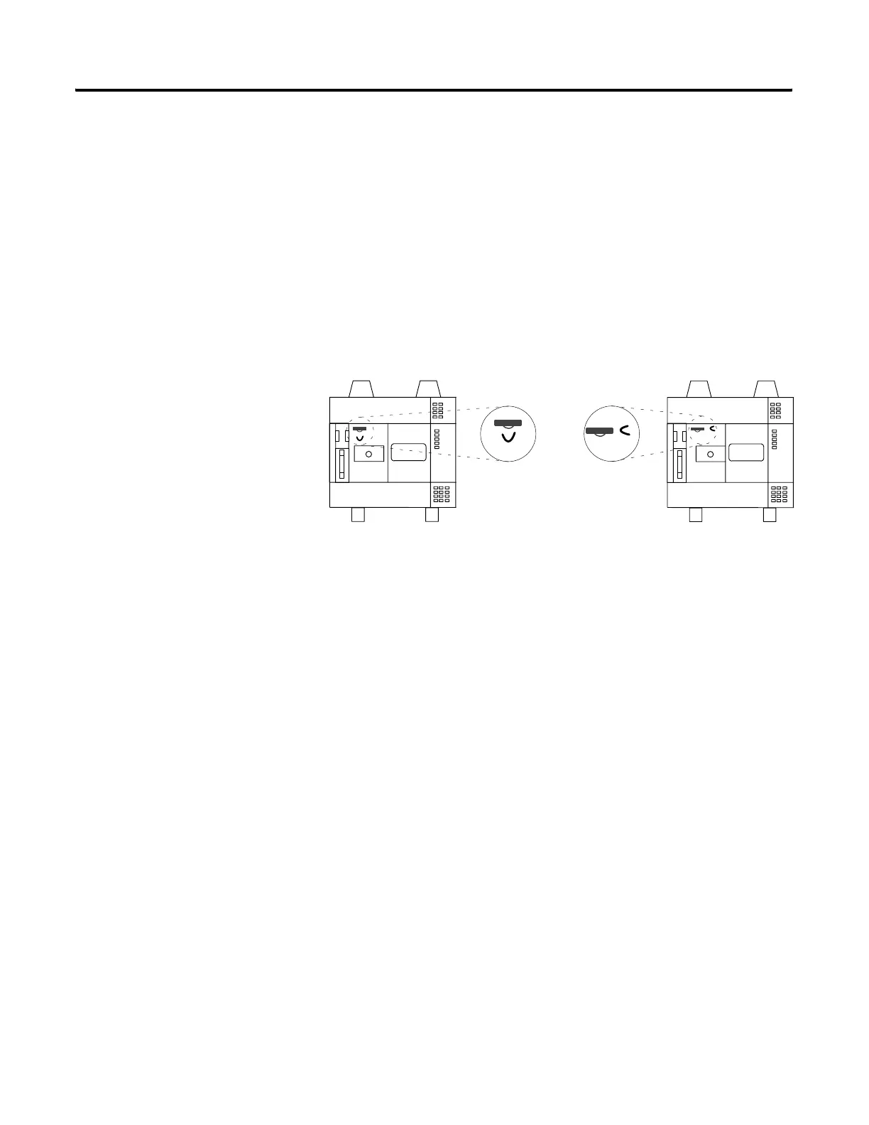
1. Turn off power to the fixed controller.
2. Remove the SLC 500 cover.
3. Locate and cut jumper wire J2. Do not remove completely but make
certain that the ends of the cut jumper wire are not touching each other.
4. Replace the cover.
Input I:0/0 then operates in the high-speed mode. The address of the
high-speed counter enable bit is C5:0/CU. When rung conditions are true,
C5:0/CU is set and transitions occurring at input I:0/0 are counted.
To begin high-speed counting, load a preset value into C5:0.PRE and enable
the counter rung. To load a preset value, do one of the following.
• Change to the REM Run or REM Test mode from another mode
• Power up the processor in the REM Run mode
• Reset the HSC using the RES instruction
Automatic reloading occurs when the HSC itself sets the DN bit on interrupt.
Each input transition that occurs at input I:0/0 causes the HSC accumulated
value to increment. When the accumulated value equals the preset value, the
Done bit (C5:0/DN) is set, the accumulated value is cleared, and the preset
value (C5:0.PRE) is loaded into the HSC in preparation for the next
high-speed transition at input I:0/0.
Your ladder program should poll the Done bit (C5:0/DN) to determine the
state of the HSC. Once the Done bit has been detected as set, the ladder
program should clear bit C5:0/DN (using the unlatch OTU instruction)
before the HSC accumulated again reaches the preset value, or the overflow
bit (C5:0/OV) will be set.
The High-speed Counter jumper is located either beneath the
battery connector OR to the right of the battery connector.

 Loading...


