Publication 1747-RM001G-EN-P - November 2008
1-6 Processor Files
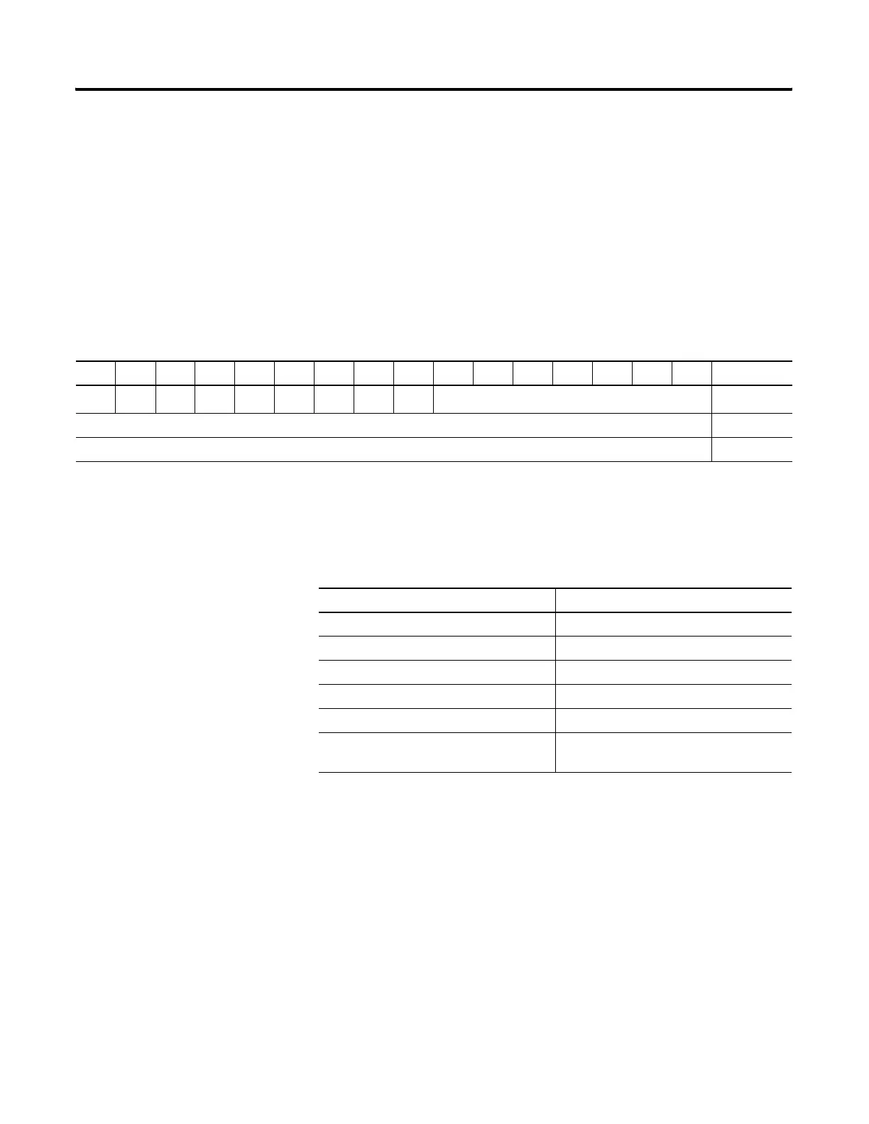
Counter Data File Elements (C5:)
Each Counter address is made of a 3-word data file element. Word 0 is the
control word, containing the status bits of the instruction. Word 1 is the preset
value. Word 2 is the accumulated value.
The control word for counter instructions includes five status bits, as indicated
below.
Table 1.7 Counter Control Fields
15 14 13 12 11 10 09 08 07 06 05 04 03 02 01 00 Word
CU CD DN OV UN
UA
(1)
Internal Use
(2)
0
Preset Value (PRE) 1
Accumulator Value (ACC) 2
(1)
Fixed SLC 500 only.
(2)
Bits labeled “Internal Use” are not addressable.
Table 1.8 Counter Elements
Addressable Bits Addressable Words
CU = Count up enable (Bit 15) PRE = Preset
CD = Count down enable (Bit 14) ACC = Accum
DN = Done bit (Bit 13)
OV = Overflow bit (Bit 12)
UN = Underflow bit (Bit 11)
UA = Update Accumulator bit (Bit 10) (Fixed
Controller Only)

 Loading...


